Magnetic Field Analysis of Hollow Halbach Long Stator Permanent Magnet Synchronous Linear Motor for Suspension Permanent Magnet Maglev Train
Article information
Abstract
In suspended permanent magnet maglev trains, the magnetic field generated by hollow-type permanent magnet synchronous linear motors is one of the main sources of low-frequency electromagnetic fields. To investigate the magnetic field generated by the linear motor in the train, this paper first establishes the 2D and 3D models of the linear motor using ANSYS EM software. Then, the electromagnetic simulation of the magnetic field of the linear motor is performed under conditions of no load and full load. Next, the magnetic field of the motor is measured using a six-channel high-precision magnetic field test system, and the simulation and measurement results are compared. The result analysis indicates that the energy distribution of the electromagnetic field generated by the linear motor is uniform and that the magnetic induction intensity falls within the range of 0 to 1.1 T. Meanwhile, the linear motor can form a closed loop with a small electromagnetic field energy leakage. Combined with its installation structure, the radiation to the surrounding environment is weak, and the interference with the normal operation of the train control communication equipment is minimal. This study lays a foundation for analyzing electromagnetic distribution on the surface of the suspended permanent magnet maglev train. It also provides a basis for formulating various electromagnetic radiation protection measures and provides theoretical support for developing suspended permanent magnet maglev trains.
I. Introduction
With the rapid development of high-speed processing and magnetic levitation technology, linear motors have gradually become a research hotspot, and the linear synchronous motor is one of the most popular motors. The linear synchronous motor runs at the same speed as the magnetic field speed, with good controllability and high efficiency. The excitation method of linear synchronous motors includes the electrically excited structure, permanent magnet structure, and hybrid excitation structure. The permanent magnet linear synchronous motor generates a magnetic field by permanent magnets, which addresses the issue of a complicated excitation structure [1–2]. In modern production, permanent magnet synchronous linear motors are widely used in transportation systems [3–5], with the advantages of high thrust density, low loss, light weight, fast response, and direct conversion of electrical energy into linear thrust [6, 7]. It can be divided into two types of structures: one with an iron core and one without an iron core. The core-type permanent magnet linear motor has a high cogging effect and end effect, and its winding core has a magnetic concentrating effect with a small air gap, making the air gap magnetic field of the motor relatively large. However, this causes problems such as poor dynamic performance of the motor, high vibration and noise, and deviation of system parameters, which affects the motor’s stability and positioning accuracy [8–10]. The coreless permanent magnet synchronous linear motor has no iron core in the armature winding, so there is zero positioning force and no cogging effect and the generated thrust is relatively stable [11, 12]. Meanwhile, due to its lack of magnetic concentration, the magnetic density of the air gap is smaller than that of the iron core, the reasoning density is also smaller, the positioning accuracy is high, the response speed is fast, and it is easier to control [13, 14].
The suspension permanent magnet maglev rail transit system is a new type of rail transportation (Fig. 1). It has the advantages of high safety and reliability, low operating noise, good environmental friendliness, strong adaptability, all-weather operation, and a small footprint [15]. It is suitable for use in urban systems and for urban–rural combinations with beautiful environments, undulating terrain, and ecological types. Currently, a 60-meter “Redrail” test line and a one-kilometer-long trial operation, “Xingguo Line,” have been constructed. The system uses rare earth permanent magnet material as a track and suspension point. Driven by the hollow Halbach long-stator permanent magnet synchronous linear motor, non-contact safety and smooth operation are realized by permanent magnet magnetic suspension. In addition, the hollow permanent magnet synchronous linear motor winding is fixed in the sky beam by epoxy resin, and the moving magnet secondary structure [16] is fixed on the train bogie to drive the train.
The suspended permanent magnet maglev train is affected by the traction power supply system and the high-power internal equipment. Low-frequency electromagnetic fields generated on top of and inside the train can interfere with the train’s control communication equipment. To investigate the effect of electromagnetic radiation generated by the hollow Halbach long-stator permanent magnet synchronous linear motor on the surrounding space, this paper uses ANSYS EM software to establish the motor model. The finite element method is used to analyze and compare the air gap magnetic field of the no-load and full-load motors. To measure the motor magnetic field of the “Redrail” line, the six-channel high-precision magnetic field test system and the low-frequency electromagnetic field online monitoring system are employed. Additionally, the simulated and measured magnetic fields are compared, and the air gap magnetic field distribution of the motor is analyzed in detail. The study results provide a basis for formulating various electromagnetic radiation protection measures and a theoretical basis for the development of suspended permanent magnet maglev trains.
II. Structure of Hollow Halbach Long Stator Permanent Magnet Synchronous Linear Motor
The structure of the hollow Halbach long stator permanent magnet synchronous linear motor is presented in Figure 2. The motor consists of two parts: the primary structure and the secondary structure. The primary structure is composed of a hollow type of coil, a nonmagnetic primary support frame, and epoxy resin. The secondary structure involves an onboard permanent magnet Halbach array and a nonmagnetic secondary support frame. The hollow primary coil is fixed on the orbital beam with epoxy resin. When the coil is connected to three symmetrical alternating currents, a traveling wave magnetic field is generated in the air gap. Combined with the induction plate laid on top of the sky beam, electromagnetic traction force is induced in the induction plate to drive the train carriage. The motor parameters are listed in Table 1.
III. The Mathematical Model of the Motor and the Principle of Finite Element Analysis
The field equation satisfied by the vector magnetic potential A in the Maxwell 2D transient magnetic field solver is:
where Hc is the coercivity of the permanent magnet, v is the velocity of the moving object, A is the vector magnetic potential, and Js is the source current density.
For a three-dimensional low-frequency transient field, Maxwell’s equations are shown below [17]:
According to equation (2), the three-dimensional transient magnetic field can be expressed as two identities:
The electromagnetic field model of the permanent magnet synchronous linear motor mainly includes the primary winding, the secondary permanent magnet, and the gap between them. The finite element model is established, and the following assumptions are made:
Permanent magnets have the same permeability in all directions, that is, μx = μy.
The air gap magnetic field is constant in the direction perpendicular to the motor movement, that is, Z-direction.
There is a wireless extension of the motor in the Y direction.
The change in the magnetic field in the Z-axis direction is ignored, and the magnetic field is simplified into a two-dimensional model.
Therefore, the finite element method is mainly used to simulate and analyze the magnetic field parallel to the motor motion direction, that is, the X-Y direction [18]. The two-dimensional electromagnetic field model of the motor can be simplified as follows:
where B is magnetic induction intensity, μ is material permeability, H is magnetic field intensity, and J is current intensity.
The mathematical model of the hollow-type permanent magnet synchronous linear motor is as follows.
The three-phase voltage equation is
The flux linkage includes the flux ψ generated by the current of the winding and the flux ψpm of the permanent magnet magnetic field passing through the winding. The flux linkage equation of the motor is:
The voltage equation in the d − q coordinate system is obtained by an intertwined coordinate transformation and theoretical derivation as:
The equation of the flux linkage equation in the d − q coordinate system is:
The electromagnetic power equation is:
In the above formula, the first item idpψd + iqpψq denotes the change rate of magnetic field energy storage, the second item r(id2 + iq2) denotes the resistance loss, and the third item (ψdiq − ψqid)ω denotes the electromagnetic conversion power.
The motor traction force equation is:
The three-phase current equation of the motor is
In electromagnetic field analysis, the relationship between the vector magnetic potential and the magnetic induction intensity is as follows:
In a two-dimensional magnetic field, the current density and the vector magnetic potential have only Z-direction components. The vector differential equation of the magnetic field is:
The magnetic induction intensity in the X and Y directions is:
Since permanent magnet synchronous linear motors generally do not have initial conditions, the boundary conditions required for electromagnetic field analysis are:
where S1 and S2 are the first and second types of boundary conditions, defining the value of Az and the normal derivative of Az on the boundary, respectively. Therefore, the distribution of the motor magnetic field can be determined by differential equations and boundary conditions [19]. The finite element calculation method is employed to solve the differential equations and obtain the distribution of the magnetic field.
IV. Finite Element Simulation Analysis and Experiment
The air gap magnetic field of the permanent magnet synchronous linear motor of the suspended permanent magnet maglev train includes a constant magnetic field and an alternating electromagnetic field, and it is difficult to analyze the magnetic field. Therefore, this paper uses Maxwell simulation software to analyze the transient field of the motor magnetic field under no-load and full-load conditions, respectively. The two-dimensional model of the motor is established according to the motor parameters, as shown in Fig. 3.
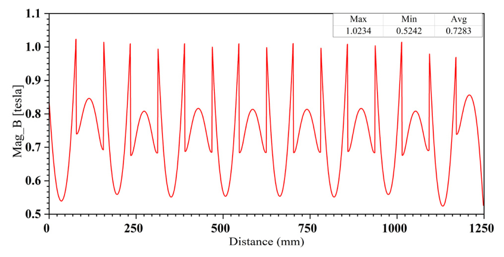
The secondary vehicle-permanent magnet of the motor consists mainly of the Halbach array of permanent vehicle magnets. Through simulation analysis, the maximum magnetic field intensity of the vehicle’s secondary permanent magnet is 1.0234 T, and the average magnetic field intensity is 0.7283 T, as shown in Fig. 4.
First, the magnetic field of the motor under the condition of no load is analyzed. The loading excitation is current, the current value is 0 A, and the three phases are the same. The balloon boundary conditions are imposed outside the domain of motor motion, and the solution domain is set to 500%. The hollow-type coil in the primary structure of the motor is copper, and the material of the nonmagnetic support frame is aluminum. In addition, the motor’s secondary structure permanent magnet grade is N48H. Second, the mesh subdivision is set up according to the corresponding solution area of the model. The time step of the simulation solution is 0.001 s, the termination time is 0.1 s, and the solution involves 100 steps. The magnetic flux density of the no-load air gap center of the motor and magnetic lines of force distribution are illustrated in Fig. 5. Meanwhile, the magnetic induction intensity in the center of the air gap is illustrated in Fig. 6.
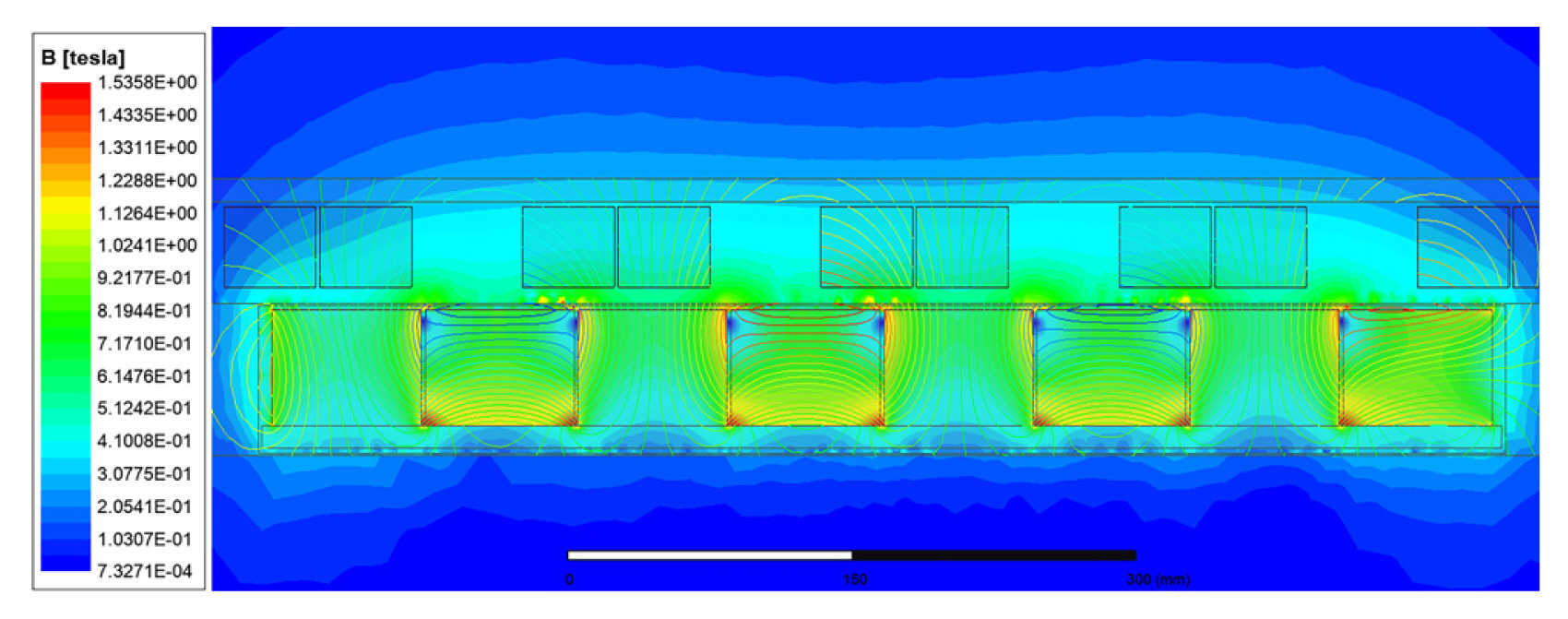
The no-load magnetic lines and air gap center magnetic flux density distribution clouds of the motor
Fig. 5 shows that the magnetic lines form a closed loop through the primary, the air gap, and the secondary of the linear motor. The electromagnetic Halbach array realizes the self-shielding of the magnetic field, and the motor energy leakage is very small. Meanwhile, the magnetic flux density distribution in the air gap center in Fig. 5 shows that the saturation region of the motor is particularly small. Only at the magnetic pole, the magnetic induction intensity in other places is in a reasonable range, indicating the rationality of the motor. Fig. 6 shows that the magnetic field distribution in the center of the air gap is relatively uniform under the no-load condition of the motor. The maximum magnetic induction intensity in the center of the air gap under the no-load condition of the motor is 1.0525 T, and the average magnetic induction intensity is 0.3807 T.
To analyze the magnetic field distribution of the motor more comprehensively, a simulation analysis of the magnetic field strength of the motor under full-load conditions is carried out. The moving magnetic field Halbach array studied in this paper adopts a three-phase structure, and the motors differ from each other by 120 electrical degrees. Therefore, the loading excitation is still current:
First, the three-phase moving magnetic field hollow Halbach long-stator permanent magnet synchronous linear motor model is established with finite element software. Then, the relevant parameters are set in turn. The magnetic field distribution of the three-phase moving magnetic field Halbach array at any time can be obtained through transient simulation calculations. Fig. 7 presents the magnetic flux density distribution at the center of the fully loaded air gap and the distribution of the magnetic force line of the motor. Figure 8 presents the distribution of the magnetic induction intensity at the center of the motor’s full-load air gap.
Fig. 7 indicates that the motor can still form a complete closed loop inside the motor under full-load conditions. Motor energy leakage is minimal in combination with the self-shielding of the secondary Halbach array. Meanwhile, the energy generated by the motor has little impact on the external environment and equipment, and its energy radiation falls within the centimeter range. The motor is installed on the train bogie, and the distance between the motor and the train carriage is greater than 2 m. Thus, the low-frequency electromagnetic field generated by the motor has very weak radiation on top of the train and inside the train, and it has little interference with the normal operation of the control and communication equipment of the train. Fig. 8 shows that the magnetic induction intensity in the center of the air gap is uniformly distributed under the full-load condition of the motor. The maximum magnetic induction in the center of the air gap under the full-load condition of the motor is 758.1852 mT, and the average magnetic induction is 340.0454 mT.
Fig. 9 shows the comparison results of the magnetic flux density at the center of the air gap under the no-load and full-load conditions of the motor obtained by finite element calculation. It can be seen from this figure that the air gap magnetic field distribution of the motor under the full-load condition is more uniform than that under the no-load condition. Also, the air gap magnetic induction intensity under the full-load condition is generally smaller than that under the no-load condition. Additionally, as the distance between the motor’s primary coil and the magnetic poles of the secondary Halbach array increases, the magnetic field energy generated by the motor decreases.

Comparison of magnetic induction intensity at the center of the air gap under the no-load and full-load conditions of a 2D motor
The low-frequency electromagnetic field generated by the motor significantly affects the peripheral equipment and the performance of the motor, and the magnetic field distribution in the center of the air gap or the electromagnetic field radiation in space can reflect the magnetic field distribution of the motor. Therefore, to better analyze the magnetic field radiation of the linear motor, a three-dimensional motor model is constructed according to the motor parameters in Table 1. Then, the magnetic field of the motor is simulated and analyzed under no-load and full-load conditions, respectively. Specifically, the simulation frequency is 20 Hz at full motor load, the transient field analysis is conducted, and the solution domain is set to 50%. A straight line in the air gap of the motor model is selected, with a length similar to that of the linear motor substructure, and located in the center of the air gap, parallel to the direction of motor motion. The magnetic induction intensity distribution in the center of the air gap is obtained by simulation, and the results are presented in Fig. 10 and 11.
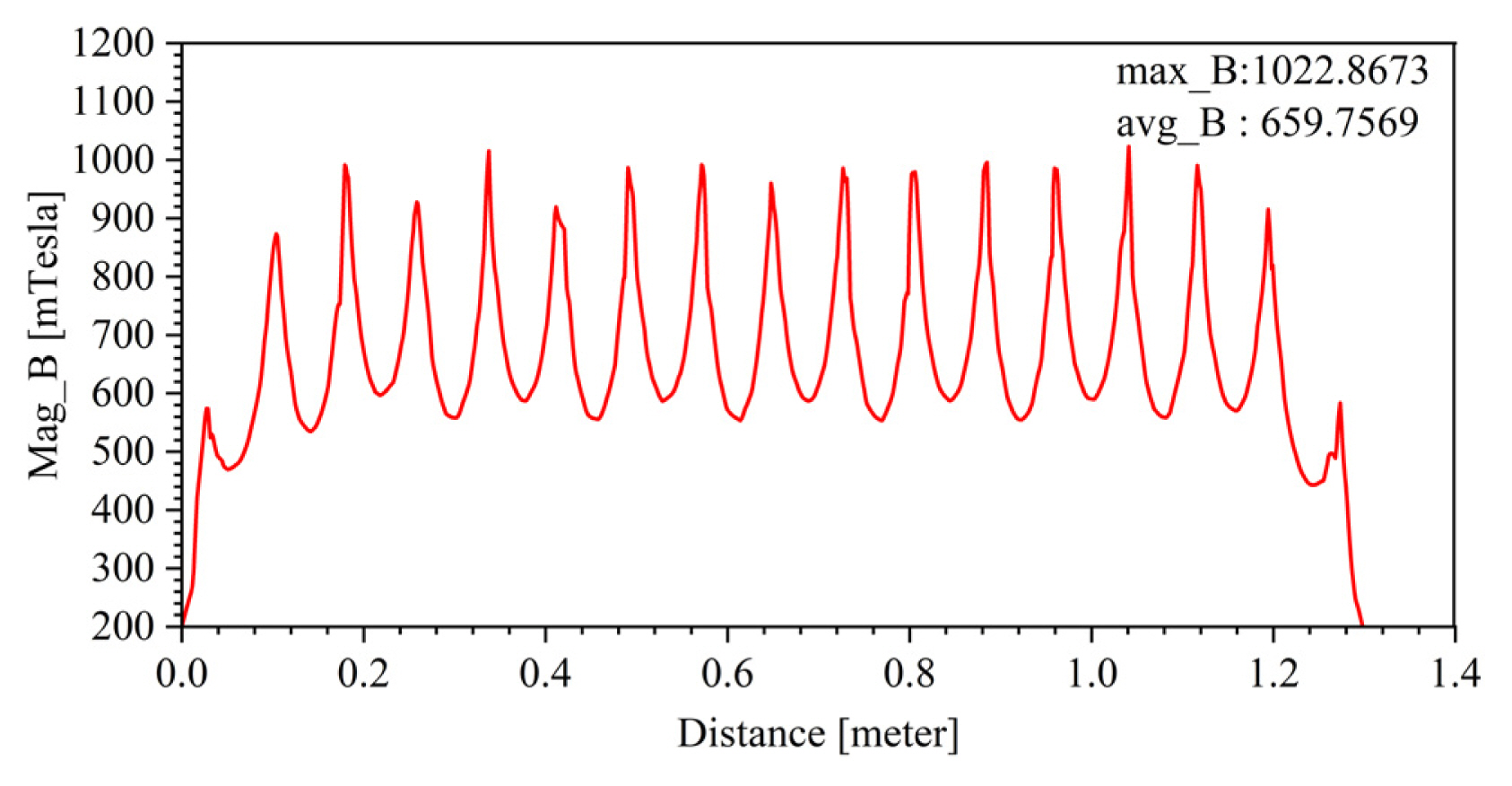
The distribution of magnetic induction intensity in the center of the air gap along the movement direction of the linear motor with no load

The distribution of magnetic induction intensity in the center of the air gap along the direction of linear motor motion at full motor load
Fig. 10 and 11 show that the magnetic field distribution of the three-dimensional linear motor is more uniform under noload and full-load conditions. Meanwhile, the maximum magnetic induction intensity in the center of the air gap under the no-load condition of the motor is 1.0229 T, and the average magnetic induction intensity is 0.6598 T. The maximum magnetic induction intensity in the center of the air gap under the full-load condition of the motor is 0.7443 T, and the average magnetic induction intensity is 0.5333 T. To investigate the main distribution of the magnetic field of the linear motor, a straight line in the air gap of the motor model is selected, whose length is equal to the width of the linear motor and is located in the center of the air gap, perpendicular to the linear motion direction of the motor. Its finite element simulation calculation results are shown in Fig. 12, which is called the longitudinal air gap magnetic field of the motor.
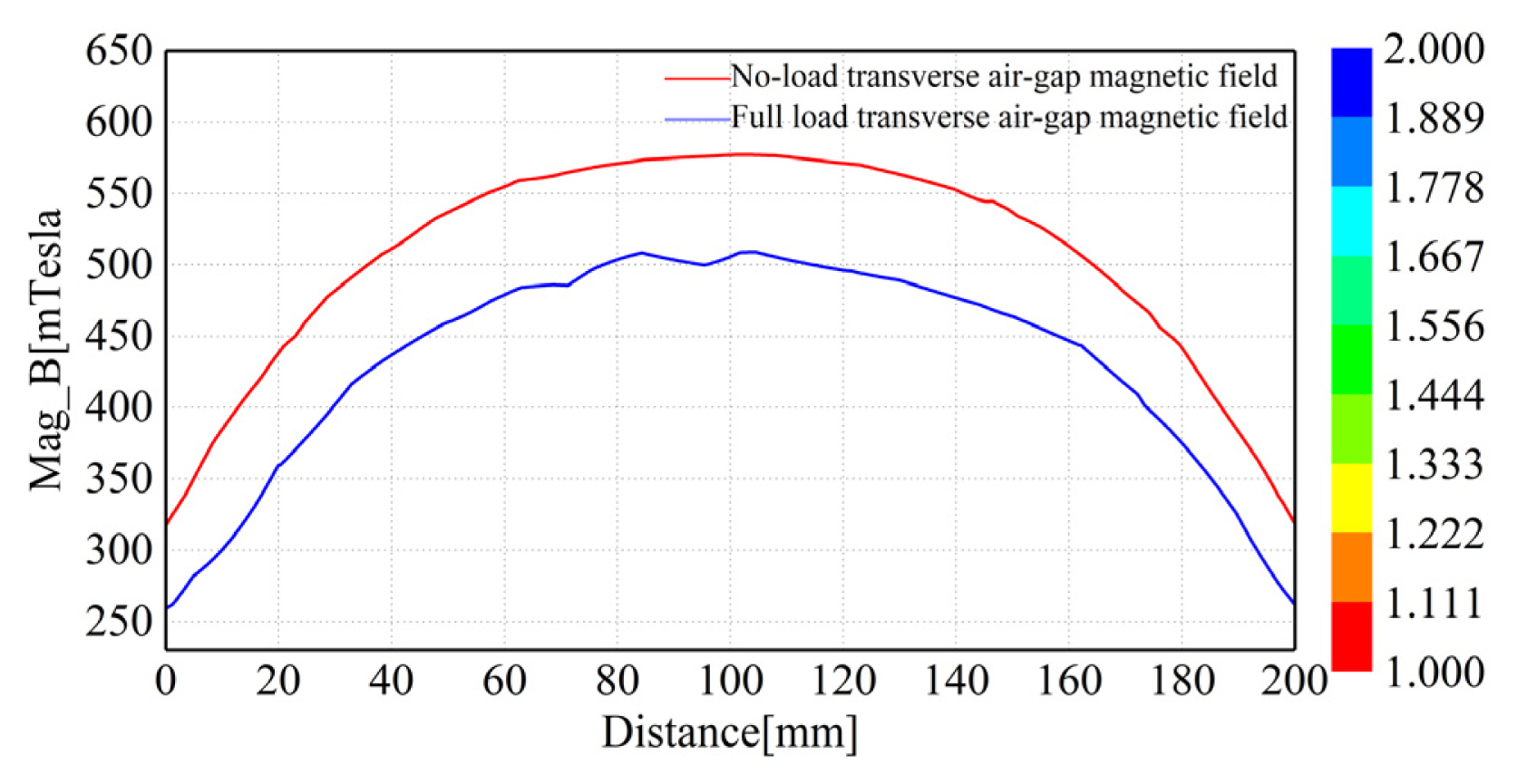
The distribution of magnetic induction intensity in the center of the longitudinal air gap under the no-load and full-load conditions of the motor
Fig. 12 shows that the distribution of the magnetic induction intensity in the air gap of the linear motor is mainly concentrated along the movement direction of the motor. A smaller component of magnetic induction intensity exists perpendicular to the direction of motor motion, and the magnetic induction intensity falls within the range of 0–0.6 T. In addition, the maximum magnetic induction in the center of the longitudinal air gap under the no-load condition of the motor is 0.5772 T, and the average magnetic induction is 0.5071 T. The maximum magnetic induction in the center of the longitudinal air gap under the full-load condition of the motor is 0.5091 T, and the average magnetic induction is 0.4348 T. According to the comparison of the finite element simulation calculation results of the motor under no-load and full-load conditions, the periodic variation law at the center of the motor air gap and the magnitude of the magnetic induction are almost the same. Additionally, the magnetic field energy generated by the motor leaks less, and the low-frequency electromagnetic field has little interference with the control and communication equipment of the train. The above finite element simulation calculation indicates that the magnetic field energy generated by the linear motor has very weak radiation to the interior of the train.
V. Experimental Analysis
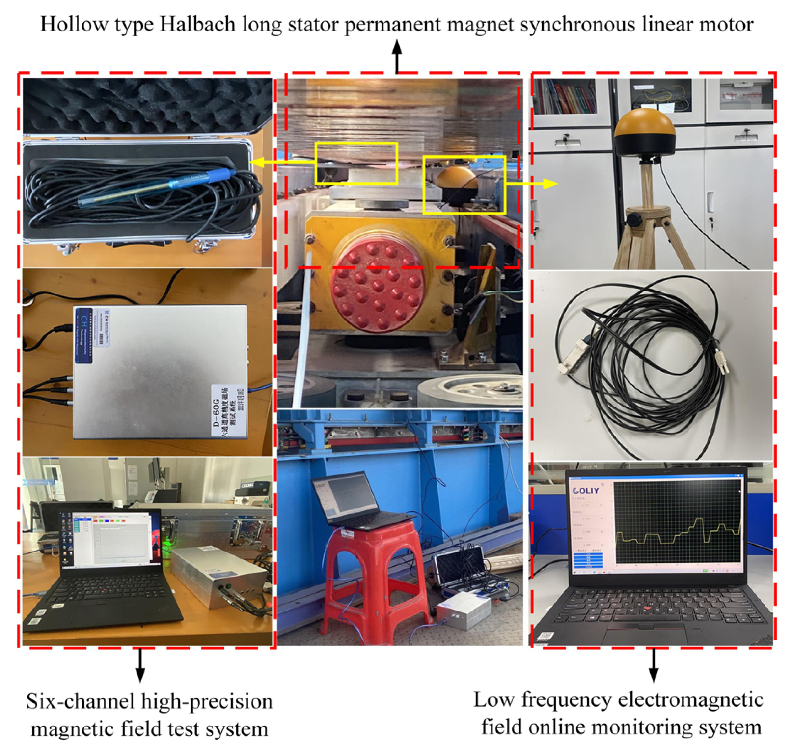
In the experiment, the six-channel high-precision magnetic field test system and the low-frequency electromagnetic field online monitoring system were used to measure the magnetic induction magnitude in the center of the motor air gap of the “Redrail” test line. The experimental equipment is illustrated in Fig. 13. The suspended permanent magnet maglev train is in a strong magnetic and electric environment, and the motor is located in a narrow space. It is difficult to test the magnetic field when a motor is running. Therefore, in this study, the air gap magnetic field is mainly measured when the motor is at rest under no load, and the air gap of the motor at the time of testing is 10 mm. The measurement results are then compared with the finite element simulation calculation results, as shown in Table 2. According to the experimental results, the maximum magnetic induction intensity at the center of the air gap of the linear motor is 1.0332 T, and the average magnetic induction intensity is 0.6640 T. The experimental measurements indicate that the magnetic field of the linear motor gradually decreases within centimeters of the linear motor, and the electromagnetic radiation generated by the linear motor gradually decreases as the distance increases. Also, the experimental results are basically consistent with the magnetic field variation of the finite element calculation results, which verifies the rationality and validity of the proposed model. It is further explained that the electromagnetic field energy generated by the hollow-type Halbach long-stator permanent magnet synchronous linear motor is mainly concentrated along the direction of motor motion, the magnetic field energy is uniformly distributed, and its magnetic field energy radiates weakly to the periphery and weakly to the interior of the train.
VI. Conclusion
In this paper, the linear motor model of the ‘Redrail’ test line of the suspended permanent magnet magnetic levitation train is established. The two-dimensional and three-dimensional models of the motor are simulated and analyzed using the finite element method, and the magnetic field distribution in the air gap of the motor is analyzed in detail using experimental measurements. The following conclusions are drawn:
The electromagnetic field energy generated by the hollow-type Halbach long stator permanent magnet synchronous linear motor is mainly concentrated in the direction of movement along the motor. The magnetic field energy is uniformly distributed, and the magnetic induction intensity falls within the range of 0–1.1 T.
The magnetic line of the linear motor forms a closed loop through the primary, the air gap, and the secondary of the motor. The Halbach array can realize the self-shielding of the magnetic field, and the magnetic field energy leakage of the motor is very small. The low-frequency electromagnetic field generated by the linear motor has weak radiation to the surrounding environment and inside the train, causing little interference with the normal work of the train control communication equipment. This can well meet the construction requirements of the permanent magnet maglev train project.
The analysis results of the air gap magnetic field of the hollow Halbach long stator permanent magnet synchronous linear motor lays a foundation for analyzing the electromagnetic distribution on the surface of the suspended permanent magnet maglev train. It also provides a basis for formulating various electromagnetic radiation protection measures and provides theoretical support for developing suspended permanent magnet maglev trains.
Acknowledgments
This work was supported by the 03 Special Project and 5G Program of the Science and Technology Department of Jiangxi Province (No. 20193ABC03A058), the Research Projects of Ganjiang Innovation Academy, the Chinese Academy of Sciences: No. E255J001, the Central Guided Local Science and Technology Funding Project of the Science and Technology Department of Jiangxi Province (Cross-regional Cooperation, 20221ZDH04052), the China Scholarship Council (CSC, No. 201708360150), the Key Foundation of Education Committee of Jiangxi (No. GJJ170493, No. GJJ190451), the Program of Qingjiang Excellent Young Talents in Jiangxi University of Science and Technology (JXUSTQJBJ2019004), the cultivation project of the State Key Laboratory of Green Development and High-Value Utilization of Ionic Rare-Earth Resources in Jiangxi Province (20194AFD44003), the Key Research and Development Plan of Ganzhou (industrial field), and the Science and Technology Innovation Talent Project of Ganzhou.
References
Biography

Yongchao Wang is currently pursuing an M.S. degree in mechanical engineering at Jiangxi University of Science and Technology, Ganzhou, China. His research direction is electromagnetic compatibility. He is currently studying the electromagnetic characteristics of a suspended permanent magnet maglev train.

Kuangang Fan was born in Linyi, China, in 1981. He received a B.S., an M.S., and a Ph.D. in instrumentation science from Jilin University in June 2006, June 2008, and June 2011, respectively. From 2012 to 2014, he held a postdoctoral position at the State Key Laboratory of Pattern Recognition, Institute of Automation, Chinese Academy of Sciences. From 2015 to 2016, he was a Visiting Scholar with the School of Electronics and Computer Engineering, Peking University Shenzhen Graduate School. From 2018 to 2019, he was a Visiting Scholar with the Department of Electrical and Computer Engineering, UC Davis, Davis, CA, USA. He is currently a professor of electrical and computer engineering at Jiangxi University of Science and Technology, China. He has published over 30 refereed articles and book chapters and holds more than 30 invention patents. His research contributions cover a broad range of signal processing and control engineering, including blind channel estimation and equalization, source separation, parameter estimation, and adaptive control. From 2012 to 2014, he was a postdoctor at the State Key Laboratory of Pattern Recognition, Institute of Automation, Chinese Academy of Sciences. From 2015 to 2016, he was a visiting scholar at the School of Electronic and Computer Engineering, Peking University Shenzhen Gratude School. From 2018 to 2019, he was a Visiting Scholar in the Department of Electrical and Computer Engineering, UC Davis, California, USA. He became a Member (M) of IEEE in 2020.

Qishou Pang was born in Shandong, China, in 1963. He is currently a professor of mechanical engineering at Jiangxi University of Science and Technology, China. His main research interests are prare earth metallurgical equipment and digital control technology.


