Built-In Coil Current Sensing for 7-Tesla 1H/23Na and 1H/31P Magnetic Resonance Imaging
Article information

Abstract
This article introduces two designs for dual-tuned built-in radio-frequency coil current sensing in 7-Tesla magnetic resonance imaging based on the current forcing property of the quarter-wave transmission line. The first design offers dual-tuned built-in coil current sensing at 1H/23Na resonant frequencies to probe the coil current consecutively at 298 MHz and 78.8 MHz, without the need for any integrated sensor on the coil. The second design enables dual-tuned built-in coil current sensing at 1H/31P resonant frequencies to probe the coil current at 298 MHz and 120 MHz consecutively. The first design achieved good matching (<−40 dB) and low insertion loss (<0.5 dB) for 1H and 23Na magnetic resonance signals. The 1H/31P design also exhibited good matching (<−30 dB) and low insertion loss (<0.67 dB). Therefore, both designs show promising potential for monitoring current flows in dual-tuned coils at the Larmor frequencies of different atomic nuclei.
I. Introduction
An increase in the static magnetic field strength (Bo) of magnetic resonance imaging (MRI) machines serves to linearly increase the signal-to-noise ratio (SNR) ∝Bo, which shortens acquisition time and improves spatial resolution [1]. In addition, doubling the field also doubles the susceptibility variation, which aids applications such as functional MRI that leverage the blood oxygen level-dependent effect. Furthermore, it doubles the chemical shift, which aids in conducting peak separation in spectroscopy [2]. However, the inhomogeneity and artifacts associated with ultrahigh field MRI are not desirable features.
Furthermore, increasing the Bo also increases the proton Larmor frequency, which leads to a decline in the wavelength of the radio-frequency (RF), causing the existing signal to fall below the human body size. In the case of 7-Tesla MRI, this wavelength reaches 15 cm inside the body and 12.5 cm inside the head. As a result, the rotating field B1 is affected by diffraction and reflection inside the body. These electromagnetic interactions lead to destructive RF interference and a strong inhomogeneous distribution of the B1 field [3, 4], both of which affect the quality of the scanned image. Moreover, the RF power deposition and its specific energy absorption rate scale quadratically along with the field strength
To address the deposition power and heating effect, it is necessary to control the SAR. This can be achieved by first measuring the current within the transmit radiofrequency coil that is responsible for generating the B1 field. In view of this, [18–24] integrated a current sensor into the transmit coil to measure its current flow. In [18], the obtained current sensing information was used to compute RF shim weights for minimizing B1 non-uniformities, while Zanchi et al. [19] controlled the coil current using a Cartesian feedback loop (FBL) without using any extra field sensor. Furthermore, Stang et al. [20] introduced a transmit-only surface coil equipped with an integrated 1:1 transformer current sensor in the resonant loop. In [21], an optically coupled current monitoring device consisting of a toroidal sensor, transmitter, and receiver was designed to display the measured signals. It also comprised a simplified version of the frequency-offset Cartesian feedback system, which offered an automatic negative feedback control system to sense and attenuate the RF wire current. By measuring the maximum allowable current that could be directed into the coil by the power amplifier (PA), this study was able to reduce the amplitude and phase distortions by about 20 dB. Furthermore, Hoult et al. [22] involved the use of electrostatic and magnetic sensors. In electrostatic sensing, a balanced capacitive potential voltage divider is used to derive part of the voltage traversing the tuning capacitors of one of the coils. Meanwhile, in magnetic sensing, a butterfly sensing loop is used for one coil and a toroidal sense winding bearing a sufficient number of turns is used for the second coil. Notably, the ability to monitor the current flow in coils enables the calculation of the array transmitter voltages required to cancel undesired induced voltages. In this context, Solbach et al. [23] presented a new conceptualization for near-magnet PAs for proton MRIs that did not necessitate the use of a circulator/ isolator and closely cooperated with the coil. This design not only allowed control of the coil current but also offered coil decoupling. For coil current sensing using this design, the PA first uses an unconventional Cartesian FBL to compensate for current variations in the array coil by controlling the output voltage of the PA [24]. The PA output is connected to the coil using a tuned (N × half-wavelength) cable, with the current flowing into the coil being independent of load impedance and proportional to the voltage at the transformer’s primary side. Furthermore, the second probe voltage at the PA matching stage is proportional to the voltage at the coil terminals [23].
This article introduces a novel concept for RF coil current sensing. Instead of employing external or integrated current sensors to measure the current flow in an RF coil, this concept relies on a special connection between the PA and the RF coil composed of multiple sections of two different transmission line lengths (quarter-wave and half-wave lengths). The first quarter-wave transmission line utilizes two probes to sample voltages across the line. Notably, these voltages are proportional to the current flowing into the RF coil and the voltage across the RF coil terminals. Both probe voltages can be used to monitor the SAR level when scanning a patient. Therefore, this conceptualization can help monitor current flows at two resonant frequencies.
The remainder of this paper is structured as follows: Section II outlines the research methods adopted to support the dual-tuned 1H/23Na and 1H/31P RF coils, Section III presents and discusses the results of the current study for both the dual-tuned built-in coil current sensing designs, and Section IV concludes the study.
II. Methodology of Built-In Coil Current Sensing
1. Design of the Built-in Coil Current Sensing Method
Traditional PAs employ several meters of long transmit cables to connect PAs located in the technical room to the RF coils in the scanner room. To address this issue, Solbach et al. [23] proposed and constructed a near-magnet PA that could be placed inside the scanner room. This PA reduced the power dissipation inside the transmit cables by shortening its distance from the RF coils. In addition, it could sense the current flowing through the RF coil without using any integrated current sensors in the coil. Notably, the authors of [23] employed the novel concept of RF coil current sensing, which is based on the current forcing property of quarter-wave transmission lines, according to which the current flow in a load (i.e., RF coil) is independent of load impedance but proportional to the input voltage of the quarter-wave transmission line. The current forcing property can be estimated from the voltage wave U(z), as shown in Fig. 1. The voltage wave for a lossless transmission line at z = l can be expressed as [25]:
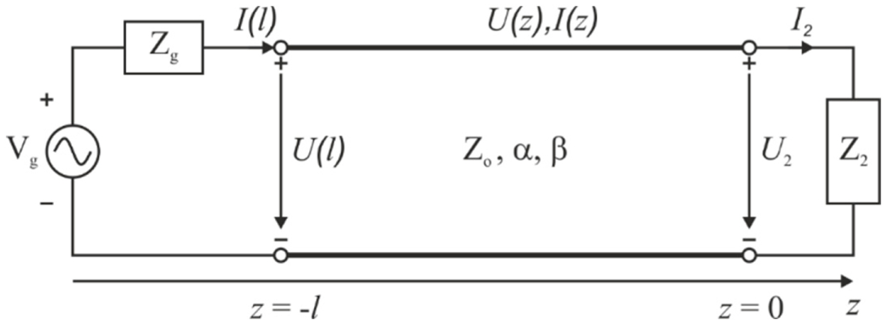
A lossy transmission line with its voltage and current definitions.
where Z2 is the load impedance, I2 is the load current, Zo is the characteristic impedance of the transmission line, β is the phase constant, and l is the length of the transmission line. However, when using a quarter wavelength transmission line, Eq. (1) becomes:
On rearranging Eq. (2), the following equation is obtained:
Eq. (3) represents the current forcing property, which refers to the proportionality between the load current and the input voltage of the quarter wave transmission line.
However, since real transmission lines are lossy, Eq. (1) should realistically be expressed as [25]:
When using a quarter wavelength transmission line, Eq. (4) becomes:
After rearranging Eq. (5), the following equation is obtained:
The proposed built-in coil current sensing based on the current forcing property, as detailed earlier, was implemented in [25], as shown in Fig. 2. At the end of the PA, two probes (UU and UI) are connected using a quarter-wave transmission line to sample the output voltage. The structure also consists of a meander-printed dipole RF coil (on the right) comprising two parallel quarter-wave transmission lines, which act as a matching network to match the 10 Ω RF coil input impedance [23, 26] with the 50 Ω transmission line impedance. Notably, the effect of biological tissues on SAR values when using the same coil geometry is explained in [27]. Furthermore, multiple half-wavelength (N × λ/2) transmission line cables are used to connect the PA to the RF coil, since the length of the cables maintains the applicability of the current forcing property. Notably, based on this property, it can be considered that the current I2 is proportional to the voltage U1, and that this voltage is equal to the voltage UI.
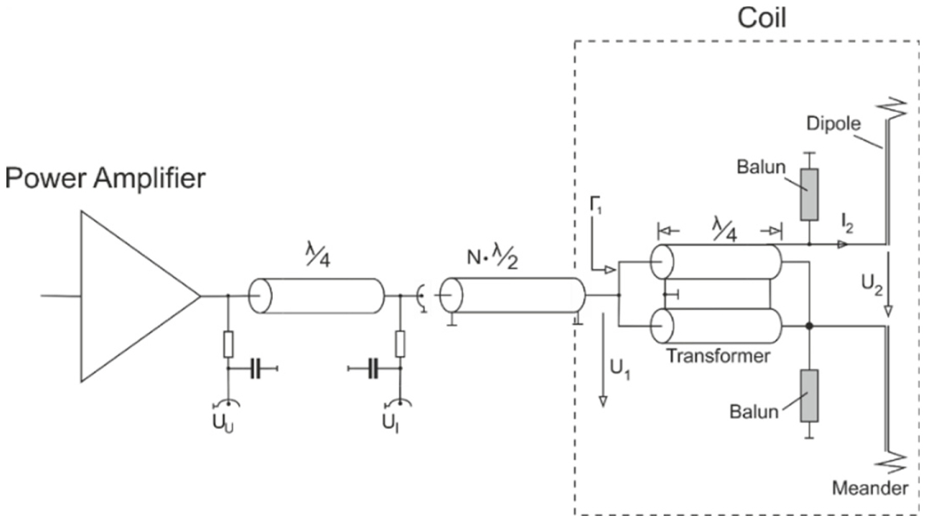
Circuit diagram of the near-magnet power amplifier with a built-in coil current sensing transmission line and a meandered RF coil.
This article builds on the concept of built-in coil current sensing by proposing a method for sensing the coil current at two different atomic nuclei (X-nuclei) resonant frequencies. This development is essential for cases in which a dual- or multi-tuned RF coil is utilized for imaging purposes. Fig. 3 depicts the circuit diagram of the dual-tuned built-in coil current sensing transmission line. With regard to the implementation of this circuit, two scenarios are explored in this study—dual-tuned built-in coil current sensing at 1H/23Na resonant frequencies and at 1H/31P resonant frequencies.
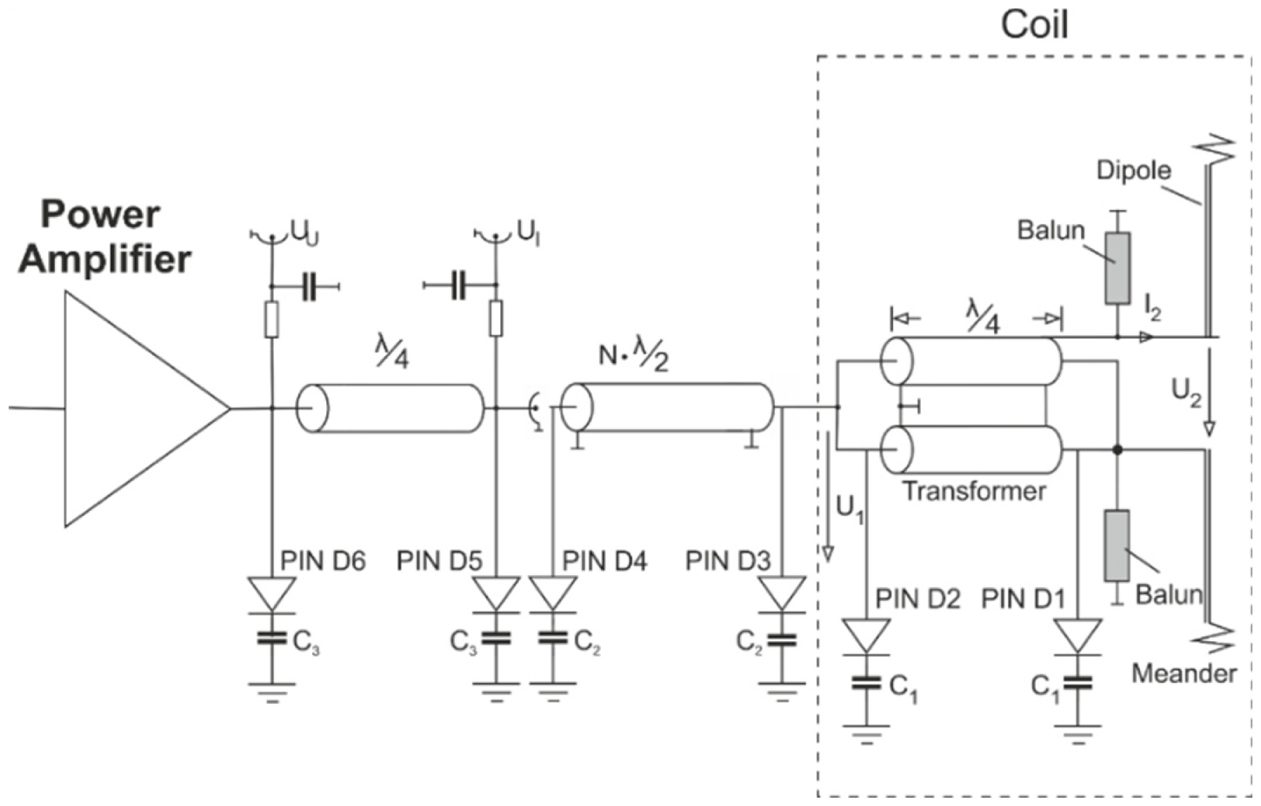
Modified circuit diagram of the built-in coil current sensing transmission line using PIN diodes and shunt capacitors (C1, C2, and C3) to sense current flows in the RF coil at two different atomic nuclei (X-nuclei) resonant frequencies.
2. Dual-Tuned Built-in Coil Current Sensing for 1H/23Na
At 1H/23Na atomic nuclei resonant frequencies, coil current sensing was accomplished at 298 MHz and 78.8 MHz. The electrical lengths of both transmission lines (λ/4 and λ/2) depicted in Fig. 3 were designed at a frequency of 99.33 MHz, thus offering a fundamental frequency at 99.33 MHz and a first odd multiple frequency at 298 MHz (1H frequency). For each transmission line section, two shunt capacitors were employed to tune the transmission line and shift the fundamental frequency to the 23Na resonant frequency (78.8 MHz). Notably, the related values of the shunt capacitors were as follows: C1 = 27.2 pF, C2 = 24.9 pF, and C3 = 13.66 pF. Furthermore, PIN diodes were used to select either of the two resonant frequencies (78.8 MHz or 298 MHz).
3. Dual-Tuned Built-in Coil Current Sensing for 1H/31P
At 1H/31P atomic nuclei resonant frequencies, coil current sensing was accomplished at 298 MHz and 120 MHz. The electrical lengths for both transmission lines (λ/4 and λ/2) in Fig. 3 were designed at a frequency of 120 MHz, which offered a fundamental frequency at 120 MHz (31P frequency) and a first odd multiple frequency at 360 MHz. For each transmission line section, two shunt capacitors were used to tune the transmission lines and shift the first odd multiple frequencies to the 1H resonant frequency (298 MHz). Notably, the values for the shunt capacitors were as follows: C1 = 22.5 pF, C2 = 15.7 pF, and C3 = 11.3 pF. Furthermore, PIN diodes were employed to select between the two resonant frequencies (120 MHz or 298 MHz).
The circuit diagram in Fig. 3 utilizes multiple half-wavelength (N × λ/2) transmission line cables along with two shunt capacitors. Notably, the specific length of the transmission line was necessary to maintain the same voltage value at the other end (the side of the PA) of the transmission line. However, this transmission line, comprising two shunt capacitors, exhibited a decline in impedance matching and increased insertion loss. To overcome these consequences, the multiple half-wavelength (N × λ/2) transmission lines were replaced with multiple double quarter-wavelength transmission lines, as shown in Fig. 4.
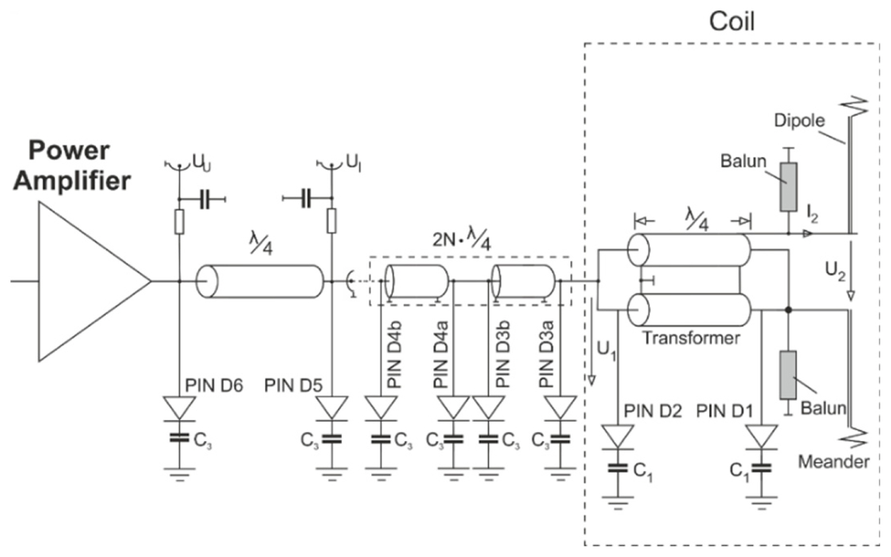
Modified circuit diagram of the built-in coil current sensing transmission line using multiple double quarter-wavelength transmission lines to sense current flows in the RF coil at two different atomic nuclei (X-nuclei) resonant frequencies.
Due to the presence of several meters of distance between the PA and the RF coil, the accuracy of the current forcing property-based coil current sensing was affected since the intermediate connected cables (N × λ/2 or 2N × λ/4) were lossy.
In the case of the lossy transmission line, the relationship between the load voltage U2 and the input voltage U1 at the half-wave transmission line terminals, as shown in Fig. 1, can be formulated as follows:
For a lossy transmission line, this relationship becomes [25]:
Notably, Eq. (8) shows that the load voltage U2 is dependent on the attenuation factor of the transmission line (α).
III. Results
1. Simulation Results
To obtain credible results, the design of the built-in coil current sensing transmission line was simulated using RG223 coaxial cables with the following parameters: characteristic impedance Zo = 50 Ω, inner conductor diameter = 0.88 mm, dielectric diameter = 2.95 mm, and attenuation factor = 0.23 dB/m at 298 MHz. The results were obtained by building the circuit diagram, depicted in Fig. 4, in Advanced Design System software using S-parameter simulation. Two S-parameter ports were used to represent the characteristic impedances of the PA (50 Ω) and the RF coil (10 Ω), as shown in Fig. 5.
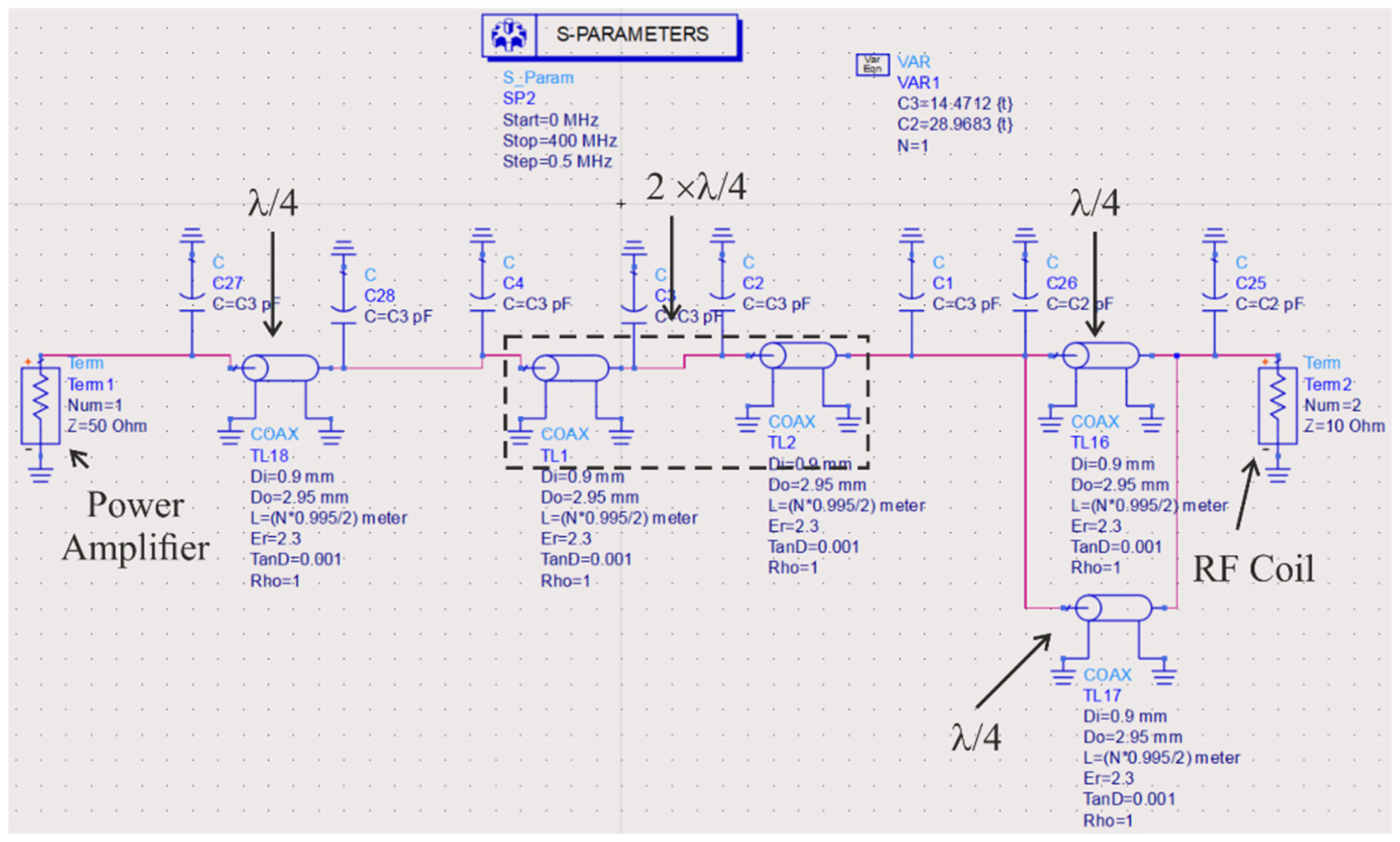
Simulation setup for 1H/23Na atomic nuclei resonant frequencies using multiple double quarter-wave length transmission lines to sense current flows in the RF coil.
Notably, two scenarios were simulated: dual-tuned built-in coil current sensing at 1H/23Na resonant frequencies and at 1H/31P resonant frequencies
1.1 At 1H/23Na atomic nuclei resonant frequencies
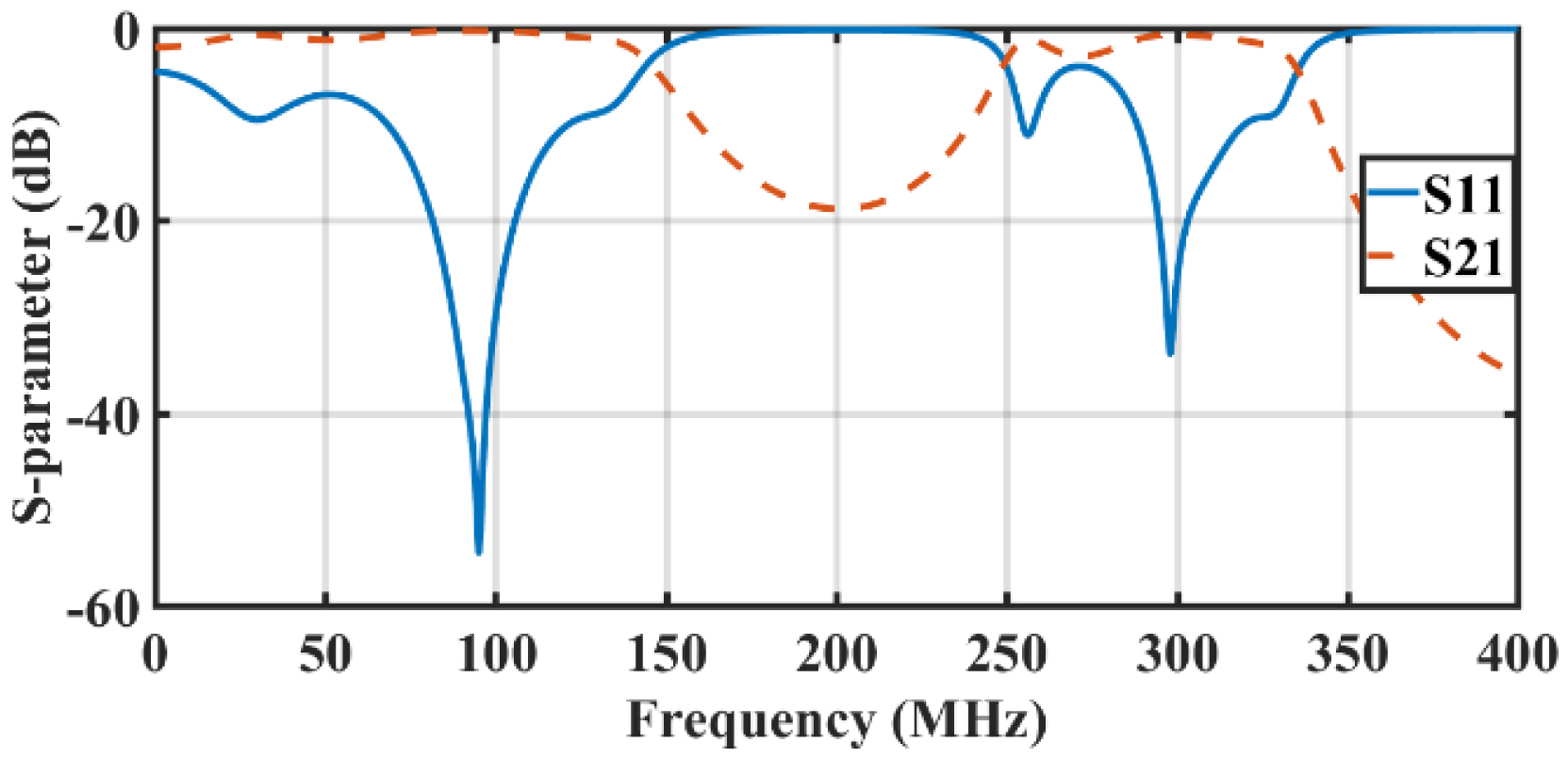
With respect to the electrical length of the coaxial cables at 99.33 MHz, two resonant frequencies (99.33 MHz and 298 MHz) were identified, as shown in Fig. 6. The simulation results showed good matching (S11 = −44.8 dB) and low insertion loss (S21 = −0.49 dB) at 1H atomic nucleus frequency (298 MHz). Furthermore, to tune the structure to the other atomic nucleus frequency for 23Na (78.8 MHz), the shunt PIN diodes were activated, with the capacitors’ values being C1 = 28.9 pF and C3 = 14.47 pF. The simulation results presented in Fig. 7 show good matching (S11 = −54.64 dB) and low insertion loss (S21 = −0.292 dB) at 23Na atomic nucleus frequency (78.8 MHz).
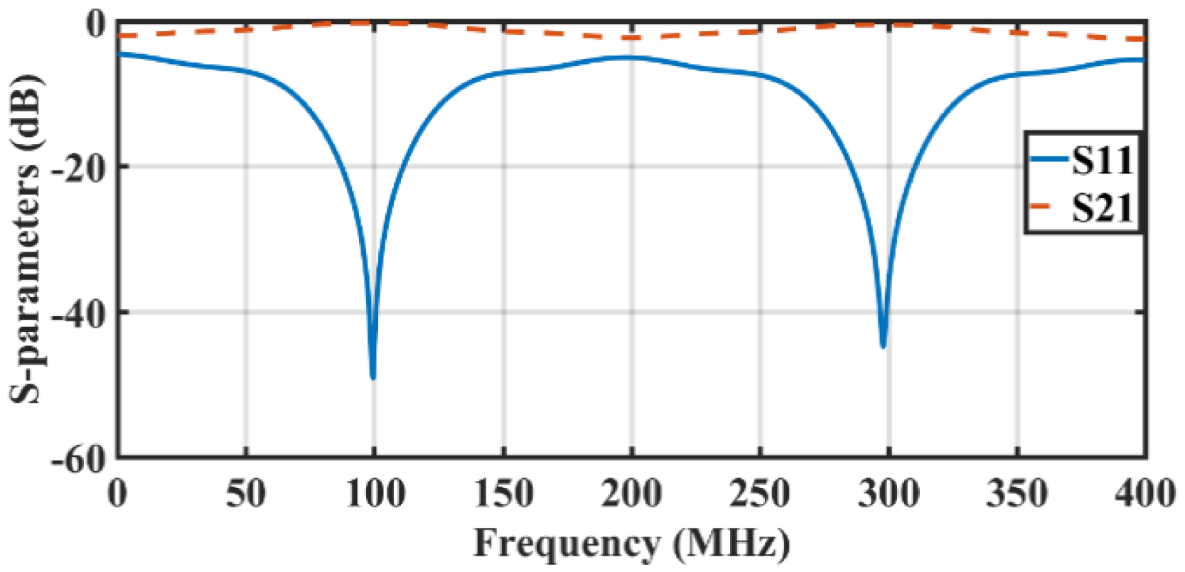
S-parameters for 1H atomic nuclei (at 298 MHz), transmission lines with electrical lengths λ/4 and λ/2 designed at 99.33 MHz frequency.
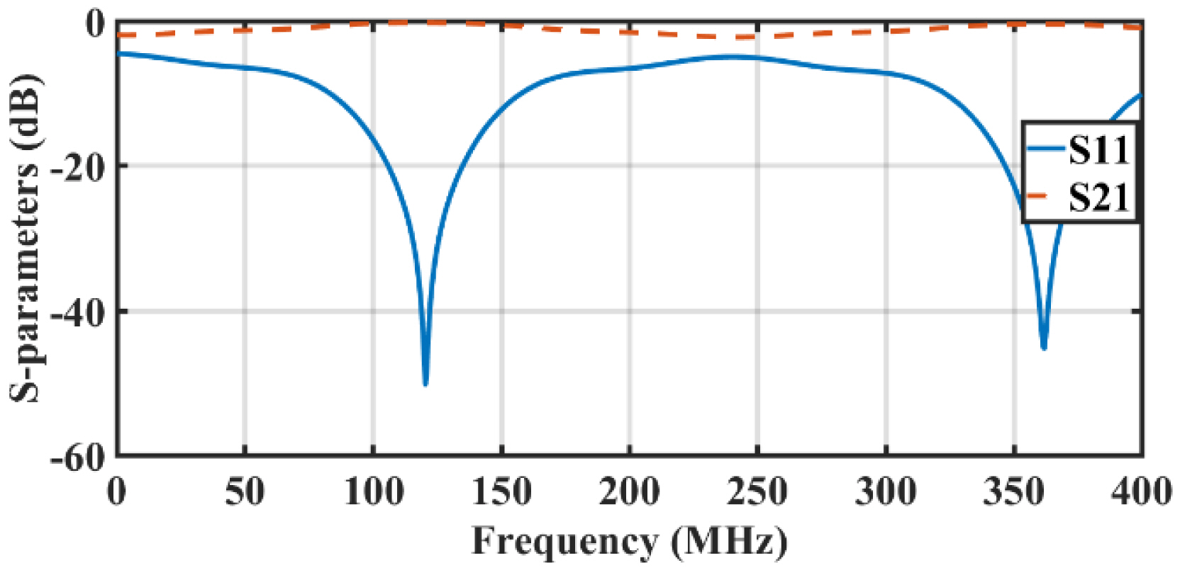
S-parameters for 23Na atomic nuclei (at 78.8 MHz) transmission lines with electrical lengths λ/4 and λ/2) designed at 99.33 MHz frequency.
1.2 At 1H/31P atomic nuclei resonant frequencies
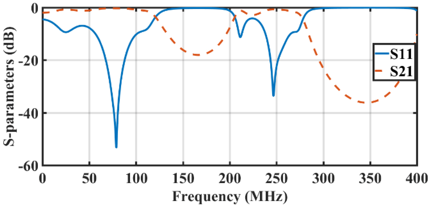
In relation to the design of the electrical length of the coaxial cables at 120 MHz, two resonant frequencies (120 MHz and 360 MHz) could be identified, as shown in Fig. 8. The simulation results showed good matching (S11 = −46.58 dB) and low insertion loss (S21 = −0.24 dB) at 31P atomic nucleus frequency (120 MHz). Furthermore, to tune the structure to the other atomic nucleus frequency for 1H (298 MHz), the shunt PIN diodes were activated, while the values for the capacitors were C1 = 24.77 pF and C3 = 12.465 pF. The simulation results illustrated in Fig. 9 show good matching (S11 = −33.83 dB) and low insertion loss (S21 = −0.669 dB) at 1H atomic nucleus frequency (298 MHz).
From these simulation results, it can be concluded that the proposed tuning method can be applied successfully in both scenarios—at 1H/23Na resonant frequencies and at 1H/31P resonant frequencies. In addition, the low insertion loss obtained in both scenarios at all resonant frequencies indicates that the current forcing property formulated in Eq. (3) applies to the novel current sensing concept proposed in this study.
2. Bench Test
To demonstrate the function of the built-in coil current sensing transmission line, a test was performed employing the PA depicted in Fig. 10(a) and the RF coil presented in [26], which were positioned close to a phantom, as shown in Fig. 10(b). Subsequently, the PA was configured to deliver 1 kW to a matched load. The voltage of the current probe was measured using an oscilloscope. Furthermore, the measurement process was repeated for different distances between the RF coil and the phantom. Notably, the measurement was conducted at 1H resonant frequency (298 MHz), with the electrical length of the transmission lines in Fig. 4 designed at 99.33 MHz, as mentioned previously.
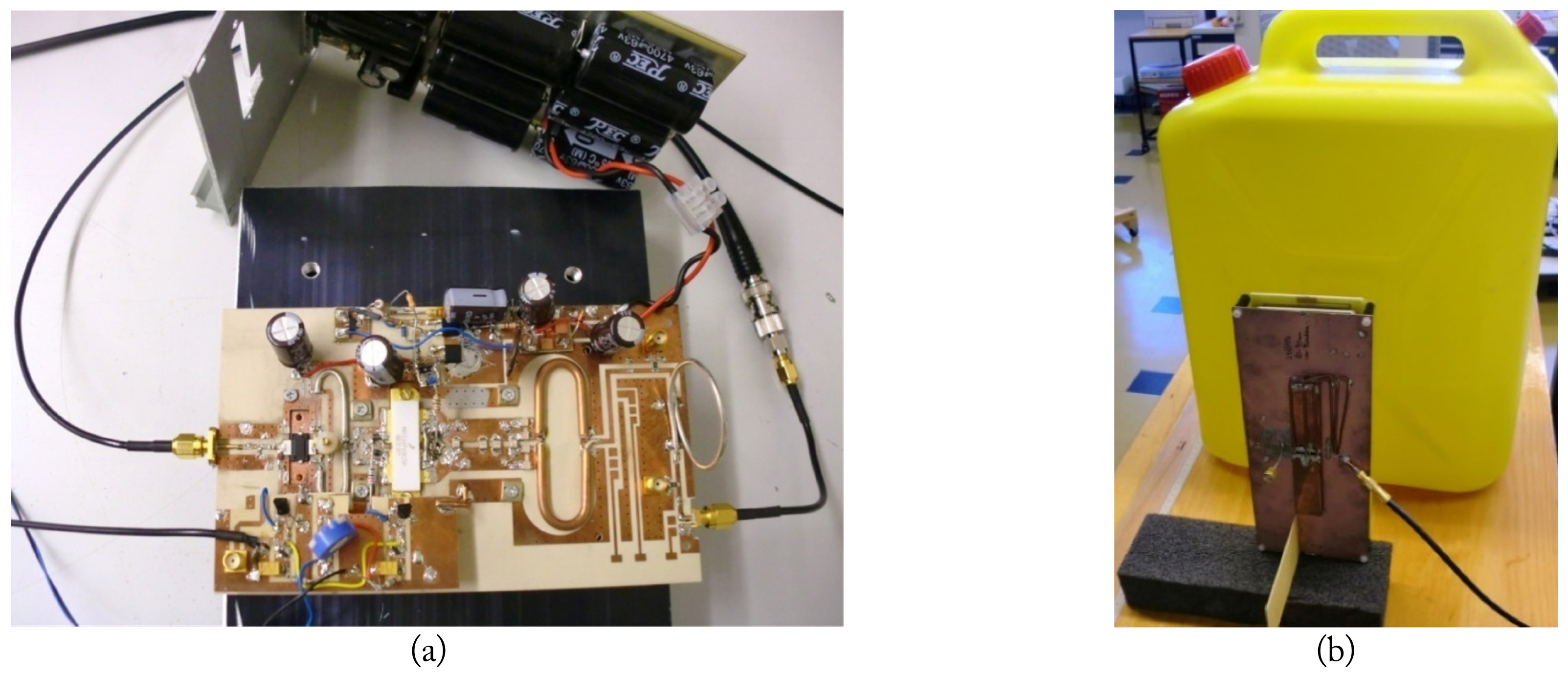
(a) A 1-kW power amplifier utilizing the current probe and (b) measurement setup to demonstrate the interaction effect between the RF coil and the phantom as a function of distance.
The measured voltages (UI) were substituted into Eq. (3) to calculate the current flow into the RF coil (I2). This current was then plotted as a function of the distance to conduct a comparison with the simulated current obtained using a current probe integrated directly into the input of the RF coil. The correlation between both currents is presented in Fig. 11, which exhibits good agreement at large distances but a reduction in correlation at small distances.
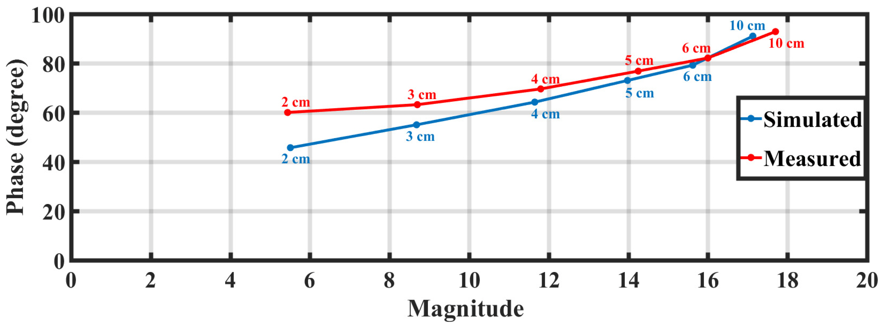
Measured and simulated current flowing into the RF coil as a function of the distance.
IV. Discussion
The accuracy of the proposed built-in coil current sensing transmission line, which is based on the property of current forcing, depends heavily on the cables. The electrical lengths of the cables should be accurately adjusted to meet the operating frequency. In addition, the accuracy of the coil current sensing can be affected by the length of the intermediate connected cables (N × λ/2 or 2N × λ/4). The near-magnet PA presented in [23] managed to reduce this length, which is expected to be between 3 m and 4 m. Notably, for lossless cables, the voltages at both ends of the half-wave cable were equal to 180° phase shifts. In contrast, for the lossy cable, the unity voltage ratio started to decrease as a function of the cable length. When using 4 m cables, the accuracy reduced to around 90% at 298 MHz, 94.4% at 78.8 MHz, and 94% at 120 MHz.
V. Conclusion
This study designed two dual-tuned built-in radio-frequency coil current sensing transmission lines for 7-Tesla magnetic resonance imaging. The first design is proposed for monitoring the current flow in a dual-tuned 1H/23Na RF coil at 298 MHz and 78.8 MHz, whereas the second design is intended to monitor the current flow in a dual-tuned 1H/31P RF coil consecutively at 298 MHz and 120 MHz. The results show that the first design achieved good matching (−44.8 to −54.64 dB) and low insertion loss (0.292 to 0.49 dB) for the 1H and 23Na magnetic resonance signals. Similarly, the second design achieved good matching (−33.83 to −46.58 dB) and low insertion loss (0.24 to 0.669 dB) for the 1H, and 31P magnetic resonance signals. Therefore, the proposed designs show great promise for application in monitoring current flow in multi-channel RF dual-resonant coils, as they reduce the need for extra integrated sensors in an MRI system.
Acknowledgments
This research was conducted at the Department of Electrical Engineering, Faculty of Engineering and Technology, of the Applied Science Private University in Amman, Jordan. The authors would like to thank the university for its unwavering support in facilitating this study.
References
Biography

Ashraf Abuelhaija, https://orcid.org/0000-0002-6645-3833 is an associate professor in the Department of Electrical Engineering at Applied Science Private University, Amman, Jordan, from where he received his B.Sc. degree in communications and electronics engineering in 2007. He received his master’s degree and Ph.D. in electrical engineering from Duisburg-Essen University in 2010 and 2016, respectively. His research interests pertain to the area of antennas and RF technology. From 2012 to 2014, he worked as a research assistant at Erwin L. Hahn Institute for Magnetic Resonance Imaging, Essen. From 2014 to 2016, he was a research assistant at the Department of Microwave and RF Technology at Duisburg-Essen University.

Gameel Saleh, https://orcid.org/0000-0003-1502-3582 was born in Aden, Yemen. He received his B.Sc. degree in electrical engineering from Aden University, Aden, Yemen, in 2001, and his M.S. degree in electrical engineering from Jordan University of Science and Technology, Irbid, Jordan, in 2008. In 2013, he was awarded a Dr.-Ing (Ph.D.) degree in electrical engineering by Duisburg–Essen University, Duisburg, Germany. From 2014 to 2015, Dr. Saleh worked in the Communication Engineering Department of Aden University. Since 2015, he has been working as an associate professor in the Department of Biomedical Engineering at Imam Abdulrahman Bin Faisal University, Dammam, Saudi Arabia. His current research interests include RF circuits, metamaterials, wearable antennas, and biosensors. Dr. Saleh was a recipient of the German Academic Exchange Service Fellowships in 2006 and 2009.

Samer Issa, https://orcid.org/0000-0003-1522-8107 received his bachelor’s degree in electronics and communication engineering in 1999 from the Applied Science Private University, Amman, Jordan. He earned a master’s degree in electrical engineering in 2003 from the University of Jordan. He worked as a teacher assistant and laboratory engineer at Applied Science Private University from 1999 to 2003 in the following laboratories: Electronics Lab, Electrical Circuit Lab, Communication and Digital Communication Lab, and Digital Electronics Lab. Since 2003, he has been a lecturer and a faculty member in the Electrical Engineering Department at Applied Science Private University, teaching electromagnetics, advanced mathematics, engineering analysis, antenna engineering, principles of electrical engineering, communication, and numerical analysis.

Osama Nashwan, https://orcid.org/0000-0002-2673-7911 is an instructor in the Department of Electrical Engineering at Applied Science Private University. He received his M.Sc. degree in electrical engineering from the University of Jordan in 2004 and his B.Sc. in communication and electronics engineering from the Applied Science Private University in 2000. His current courses include digital signal processing, probability and random variables, analog communications, and many other subjects. He has made significant contributions to many academic and administrative committees, both within and beyond the department. He is responsible for the foundation of new laboratories and upgradation of existing laboratories in the department.

Sanaa Salama, https://orcid.org/0000-0001-9480-6985 received her B.Sc. degree in Telecommunication Technology from the Arab American University (AAUP), Palestine, in 2006 (excellent evaluation, GPA 3.96/4), and her M.Sc. degree in electrical engineering from the University of Jordan, Jordan, in 2009 (excellent evaluation, GPA 3.83/4). In 2015, she received her Ph.D. degree in electrical engineering from Duisburg-Essen University in Germany. Her research interests include characteristic chassis wave modes, MIMO antenna design, beam-forming antenna array design, reconfigurable antennas, coupling element-based antenna structures, mutual coupling, chassis wave-mode coupling, and port and pattern isolation. Her recent field of research is the design of RF coils for 7 T MRI systems, design of decoupling and matching networks, and the design of implantable antennas for MICS and ISM bands. Since 2015, she has been an assistant professor in the Department of Telecommunication Engineering at AAUP. She has also authored a number of conference and journal papers.