J. Electromagn. Eng. Sci Search

CLOSE


J. Electromagn. Eng. Sci > Volume 24(2); 2024 > Article
Park, Qu, Park, and Jung: Design of a Circularly Polarized Planar Monopole Antenna with a Simplified Radiator Structure for UWB Applications

Abstract

The demand for wideband circularly polarized (CP) antennas in wireless communication applications has been increasing, given that it offers reliable signals with reduced interference. In particular, planar monopole antennas are a popular choice for use in CP applications due to their compact size and ease of integration. However, achieving CP characteristics often requires complex modifications, an increased antenna size, and design complexity. To address these challenges, this study proposes a simplified radiator structure modification for CP planar monopole antennas and validates the performance of the proposed antenna for ultra-wideband (UWB) applications by conducting both frequency-domain and time-domain analyses. The size of the proposed antenna is 34 mm × 41 mm × 1.6 mm, with FR-4 as the substrate. Both the −10 dB S11 bandwidth and 6 dB axial ratio axial ratio is 3.46–5.5 GHz, with the radiation patterns in the frequency range of interest being omni-directional. The proposed UWB CP antenna also yields decent antenna performance in time-domain analyses, such as the antenna fidelity factor and the system fidelity factor.

I. Introduction

In recent years, a growing interest in the research and development of circularly polarized (CP) antennas for wireless communication across diverse environments, including industrial, medical, and household settings [13], has been observed. Notably, CP antennas offer significant advantages over linear polarized antennas due to their ability to provide reliable and robust signals. Furthermore, they excel at reducing interference from neighboring channels or unwanted signals, leading to enhanced signal quality and a stable connection. These features have made CP antennas highly desirable for wireless communication systems in multipath environments, such as ultra-wideband (UWB)-based indoor positioning systems.
Planar monopole antennas have emerged as a prominent choice for CP antennas due to its compact size, low profile, and wideband characteristics. These antennas are particularly well suited for a variety of wideband applications that involve limited space because they can be seamlessly integrated into devices [47].
Extensive research exploring different configurations of planar monopole antennas has been conducted by numerous researchers with the aim of achieving circular polarization. For instance, former studies have attempted to determine the lowest operating frequency by employing a voltage standing wave ratio of 2 and have investigated the antennas’ bandwidth by replacing the radiator area with an equivalent cylinder [8]. However, to achieve circular polarization, the radiator of the planar monopole antenna often requires either complicated shape deformations or the incorporation of arbitrary elements. Unfortunately, these approaches contribute to increasing the antenna size, further complicating the design process [9]. In light of the previously mentioned challenges, this study proposes a CP planar monopole antenna designed for UWB applications in multipath environments. The proposed antenna involves implementing straightforward modifications to the radiator structure with the objective of overcoming the complexity associated with achieving CP characteristics. Furthermore, this study validates the proposed CP planar monopole antenna by conducting frequency-domain analyses, examining its reflection coefficient, axial ratio, and radiation patterns. Additionally, an analysis of the characteristics pertaining to the time domain, which have received limited attention in existing UWB CP antenna literature, is also carried out, since time-domain analyses, such as the antenna fidelity factor and system fidelity factor, are of great importance for UWB applications [1012].

II. Antenna Design and Measurement

The target frequency range of the proposed antenna was established between 3.7 GHz and 4.8 GHz, specifically focusing on UWB channels 2 and 3 [13]. First, a planar monopole antenna was designed based on a circular disc monopole using the formulation presented in [11], which is as follows:
(1)
fL=3×108×0.24(l+r+p)ɛr.eff,
where l is the length of the radiator, r is the radius of the equivalent cylinder corresponding to the radiator, p is the gap between the radiator and the transmission line and ɛr.eff is the effective dielectric constant.
As for the substrate in the antenna design, FR-4 of 1.6 mm thickness was employed, while the transmission line of the antenna was designed as the microstrip line. The size of the entire antenna was 34 mm × 41 mm, while the microstrip line had a width of 3 mm and a length of 12 mm. Notably, the initial design of the proposed antenna included a donut-shaped radiator to achieve circular current distribution. However, the current distribution failed to form a circle, as it usually does in an ideal donut-shaped monopole antenna. Instead, the current was distributed on both the left and right sides, causing linear polarization. To address this limitation, a novel CP monopole antenna was developed by removing the third quadrant from the donut shape, with length l and gap p being 27.7 mm and 1.4 mm, respectively. The width of the radiator was kept at 7.5 mm on account of the trade-off between the bandwidth and the axial ratio.
Fig. 1 presents the designed and fabricated antenna, while Fig. 2 illustrates the surface current distribution of the proposed antenna at 4 GHz. In Fig. 2, the prevailing surface currents are indicated by the black arrows at 90° phase intervals, highlighting their dominant direction and magnitude. Furthermore, the polarization characteristics of the proposed antenna show right-handed circular polarization in the +z direction and left-handed circular polarization in the −z direction. The measured −10 dB S11 bandwidth of the proposed antenna was 3.46–5.5 GHz. Notably, the discrepancies between the measurement and simulation results can be attributed to errors in the manufacturing and measurement processes. Fig. 3 illustrates the measured 6 dB axial ratio of the proposed antenna, which spans from 3 to 5.9 GHz. Additionally, Fig. 4 traces the radiation patterns of the antenna at three distinct frequencies. It is evident that the patterns demonstrate omnidirectional characteristics, with a maximum measured realized gain of 4.3 dBi observed at 4.5 GHz.

III. Time-Domain Analysis

This section investigates the performance of the proposed antenna in the time domain using CST Studio Suite electromagnetic simulations. The antenna fidelity factor between the input pulse and the radiated E-fields was calculated. Furthermore, to investigate circular polarization characteristics, a cross-correlation analysis of the input pulse and both the phi and theta components of the radiated E-fields was conducted.
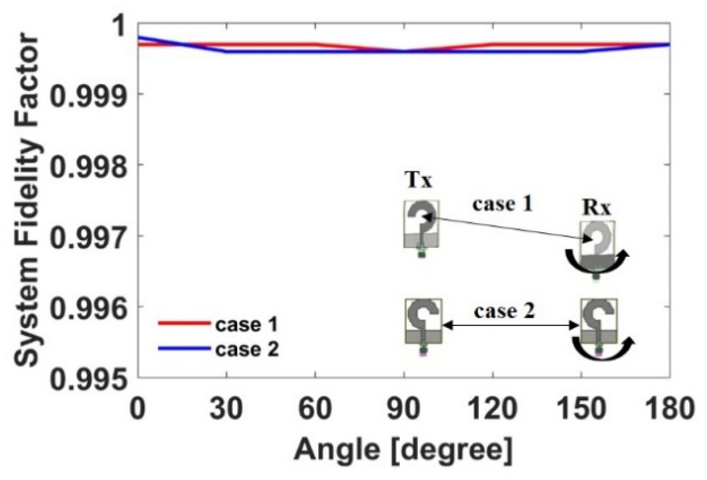
Fig. 5 displays a high antenna fidelity factor for both the phi and theta components. Notably, the system fidelity factor was computed through a cross-correlation between the transmitted and received pulses. To validate the system fidelity factor, two identical proposed antennas were positioned 500 mm apart, accounting for both face-to-face and side-by-side configurations. Additionally, the receiving antenna was simulated while rotating incrementally at 30° intervals. Fig. 6 depicts the input pulse and received pulse for the two configurations and Fig. 7 demonstrates a high value for the system fidelity factor performances. Table 1 presents a summary of a comparative analysis of the proposed antenna with conventional wideband CP antennas, with λ0 being the wavelength in free space. It is noted that the proposed antenna has very good performance in both antenna fidelity factor and system fidelity factor.

IV. Conclusion

This study presents a CP planar monopole antenna and analyzes its performance in both frequency and time domains. By implementing simple modifications to the radiator structure, the proposed antenna was able to overcome the complexities associated with achieving circular polarization while maintaining a compact size and minimum design complexity. The surface current distribution revealed that the desired circular polarization characteristics had been achieved. Furthermore, according to the results of the time-domain analysis, the proposed antenna exhibits commendable fidelity factors. In addition, the experimental results confirmed the effectiveness of the design, with circular polarization observed across a frequency range of 3.46–5.5 GHz, which satisfied both the −10 dB S11 bandwidth and the 6 dB axial ratio at the same time. Moreover, the omnidirectional radiation pattern and a maximum measured realized gain of 4.3 dBi demonstrate the suitability of the proposed antenna for UWB applications requiring reliable signal transmission and interference reduction.

Fig. 1
Schematics and fabrication.
jees-2024-2-r-214f1.jpg
Fig. 2
Surface current distribution at 4 GHz.
jees-2024-2-r-214f2.jpg
Fig. 3
Reflection coefficient and axial ratio.
jees-2024-2-r-214f3.jpg
Fig. 4
Radiation patterns: (a) xz-plane and (b) yz-plane.
jees-2024-2-r-214f4.jpg
Fig. 5
Antenna fidelity factor.
jees-2024-2-r-214f5.jpg
Fig. 6
Normalized input and received pulse signals in the time domain: (a) face-to-face case and (b) side-by-side case.
jees-2024-2-r-214f6.jpg
Fig. 7
System fidelity factor.
jees-2024-2-r-214f7.jpg
Table 1
Comparison results of the proposed antenna with those in the reference literature
Study Size (mm3) 6 dB axial ratio and −10 dB S11 bandwidth (GHz) Antenna fidelity factor System fidelity factor
This work 34 × 41 × 1.6 (0.392λ0 × 0.473λ0 × 0.019λ0) 3.46–5.50 0.931–0.969 0.9995–0.9996
Le et al. [1] 48 × 48 × 3.04 (0.752λ0 × 0.752λ0 × 0.048λ0) 4.7–6.6 N/A N/A
Park & Jung [2] 1002π × 153 (0.252λ0 × 0.962λ0) 0.6–1.7 N/A N/A
Kesavan et al. [3] 20 × 20 × 1.52 (1.96λ0 × 1.96λ0 × 0.149λ0) 29.3–31.5 N/A N/A
Zhang et al. [4] 24 × 25 × 1 (0.344λ0 × 0.358λ0 × 0.014λ0) 4.3–7.3 N/A N/A
Tang et al. [6] 49 × 55 × 1.5 (0.368λ0 × 0.413λ0 × 0.011λ0) 2.25–7.35 N/A N/A
Tao et al. [7] 25 × 25 × 1 (0.375λ0 × 0.375λ0 × 0.015λ0) 4.5–9.7 N/A N/A
Baard et al. [11] 1822π × 126 (0.2122λ0 × 0.461λ0) 0.35–5.50 N/A 0.62
Kushwaha et al. [12] 50 × 45 × 1.6 (0.367λ0 × 0.331λ0 × 0.012λ0) 2.2–5.6 N/A 0.818–0.890

References

1. T. T. Le, H. H. Tran, and A. A. Althuwayb, "Wideband circularly polarized antenna based on a non-uniform metasurface," Applied Sciences, vol. 10, no. 23, article no. 8652, 2020. https://doi.org/10.3390/app10238652
crossref
2. S. Park and K. Y. Jung, "Design of a circularly-polarized UHF antenna for partial discharge detection," IEEE Access, vol. 8, pp. 81644–81650, 2020. https://doi.org/10.1109/ACCESS.2020.2991158
crossref
3. A. Kesavan, M. A. Al-Hassan, I. Ben Mabrouk, and T. A. Denidni, "Wideband circular polarized dielectric resonator antenna array for millimeter-wave applications," Sensors, vol. 21, no. 11, article no. 3614, 2021. https://doi.org/10.3390/s21113614
crossref pmid pmc
4. L. Zhang, Y. C. Jiao, Y. Ding, B. Chen, and Z. B. Weng, "CPW-fed broadband circularly polarized planar monopole antenna with improved ground-plane structure," IEEE Transactions on Antennas and Propagation, vol. 61, no. 9, pp. 4824–4828, 2013. https://doi.org/10.1109/TAP.2013.2267719
crossref
5. T. H. Kim, Y. Kim, T. H. Yoo, and J. G. Yook, "Wideband planar monopole antenna for digital TV reception and UHF band communications," IET Microwaves, Antennas & Propagation, vol. 12, no. 13, pp. 2041–2045, 2018. https://doi.org/10.1049/iet-map.2018.5076
crossref
6. H. Tang, K. Wang, R. Wu, C. Yu, J. Zhang, and X. Wang, "A novel broadband circularly polarized monopole antenna based on C-shaped radiator," IEEE Antennas and Wireless Propagation Letters, vol. 16, pp. 964–967, 2016. https://doi.org/10.1109/LAWP.2016.2615159
crossref
7. S. Tao, M. Xu, Z. Ding, Z. Wu, H. Wang, and Y. Wang, "A wideband circularly polarized monopole antenna with elliptic ring slot patch using characteristic mode analysis," International Journal of RF and Microwave Computer-Aided Engineering, vol. 32, no. 12, article no. e23502, 2022. https://doi.org/10.1002/mmce.23502
crossref pdf
8. Y. Y. Sun, S. W. Cheung, and T. I. Yuk, "Planar monopoles with different radiator shapes for UWB body-centric wireless communications," Journal of Engineering, vol. 2013, article no. 683428, 2013. https://doi.org/10.1155/2013/683428
crossref pdf
9. I. Nadeem, M. Alibakhshikenari, F. Babaeian, A. A. Althuwayb, B. S. Virdee, L. Azpilicueta, and et al, "A comprehensive survey on ‘circular polarized antennas’ for existing and emerging wireless communication technologies," Journal of Physics D: Applied Physics, vol. 55, no. 3, article no. 033002, 2021. https://doi.org/10.1088/1361-6463/ac2c36
crossref pdf
10. S. Park and K. Y. Jung, "Novel compact UWB planar monopole antenna using a ribbon-shaped slot," IEEE Access, vol. 10, pp. 61951–61959, 2022. https://doi.org/10.1109/ACCESS.2022.3182443
crossref
11. C. Baard, Y. Liu, and N. Nikolova, "Ultra-wideband low-cost high-efficiency cavity-backed compound spiral antenna," Electronics, vol. 9, no. 9, article no. 1399, 2020. https://doi.org/10.3390/electronics9091399
crossref
12. N. Kushwaha, R. Kumar, and R. V. S. Ram Krishna, "Design and analysis of CPW-fed wideband circularly polarized antenna for modern communication systems," Journal of Electromagnetic Waves and Applications, vol. 29, no. 11, pp. 1397–1409, 2015. https://doi.org/10.1080/09205071.2015.1034808
crossref
13. D. Coppens, A. Shahid, S. Lemey, B. Van Herbruggen, C. Marshall, and E. De Poorter, "An overview of UWB standards and organizations (IEEE 802.15. 4, FiRa, Apple): interoperability aspects and future research directions," IEEE Access, vol. 10, pp. 70219–70241, 2022. https://doi.org/10.1109/ACCESS.2022.3187410
crossref

Biography

jees-2024-2-r-214f8.jpg
Seungyong Park, https://orcid.org/0009-0001-3053-3380 received his BS degree from the School of Information and Communication Engineering in Chungbuk University, Cheongju, Republic of Korea, in 2016, and his Ph.D. degree in electronic engineering from Hanyang University, Seoul, Republic of Korea. He is currently a postdoctoral researcher at Hanyang University. His research interests include UWB antennas, millimeter-wave arrays, RF circuits, and antenna design for next generation wireless communication systems.

Biography

jees-2024-2-r-214f9.jpg
Longyue Qu, https://orcid.org/0000-0001-5152-091X received his M.S. and Ph.D. degrees in electromagnetics and microwave engineering from Hanyang University, Seoul, Republic of Korea, in 2015 and 2018, respectively. He was a post-doctoral researcher at Hanyang University from September 2018 to August 2019, after which he was promoted to Assistant Research Professor. He is also the co-founder and CTO of Hanyang Antenna Design Co. Ltd., Shenzhen, China (2019 to 2022). Since 2022, he has been working as an assistant professor in the School of Electronics and Information Engineering, Harbin Institute of Technology, Shenzhen, China. Qu has authored over 50 articles and is credited with more than 30 inventions. He is a reviewer for several international journals and conferences and is also an editorial board member of the International Journal of Sensors, Wireless Communications, and Control. His current research interests include antenna theory and design, metamaterial-based antenna technology, millimeter-wave arrays, and RF circuits. Qu is a recipient of the Korean Government Scholarship Award and the China Scholarship Council. His research was listed in the Top 100 National R&D Excellence Awards in 2015.

Biography

jees-2024-2-r-214f10.jpg
Min-Seok Park, https://orcid.org/0009-0000-0804-0929 received his B.S. degree from the Department of Electrical Engineering at Myongi University, Yongin, Republic of Korea, in 2015, and his M.S. degree in electrical engineering from Hanyang University, Seoul, Republic of Korea, in 2017. From 2018 to 2020, he participated in EM-Tech’s circuit and product development as a researcher. He is currently pursuing a Ph.D. degree in electronic engineering at Hanyang University. His current research interests include computational electromagnetics, wave propagation, and multi-physics.

Biography

jees-2024-2-r-214f11.jpg
Kyung-Young Jung, https://orcid.org/0000-0002-7960-3650 received his B.S. and M.S. degrees in electrical engineering from Hanyang University, Seoul, Republic of Korea, in 1996 and 1998, respectively. In 2008, he received his Ph.D. degree in electrical and computer engineering from Ohio State University, Columbus, USA. From 2008 to 2009, he was a postdoctoral researcher at Ohio State University. Subsequently, from 2009 to 2010, he worked an assistant professor in the Department of Electrical and Computer Engineering, Ajou University, Suwon, Republic of South Korea. Since 2011, he has worked at Hanyang University, where he is now a professor in the Department of Electronic Engineering. His current research interests include computational electromagnetics, bioelectromagnetics, and nanoelectromagnetics. Dr. Jung received a Graduate Study Abroad Scholarship from the National Research Foundation of Korea, a Presidential Fellowship from Ohio State University, a HYU Distinguished Teaching Professor Award from Hanyang University, and an Outstanding Research Award from the Korean Institute of Electromagnetic Engineering and Science.

ABOUT
ARTICLE CATEGORY

Browse all articles >

BROWSE ARTICLES
AUTHOR INFORMATION
Editorial Office
#706 Totoo Valley, 217 Saechang-ro, Yongsan-gu, Seoul 04376, Korea
Tel: +82-2-337-9666    Fax: +82-2-6390-7550    E-mail: admin-jees@kiees.or.kr                

Copyright © 2024 by The Korean Institute of Electromagnetic Engineering and Science.

Developed in M2PI

Close layer
prev next