Detection of Buried Nonlinear Targets Using DORT
Article information
Abstract
Ground-penetrating radars (GPR) based on a variety of techniques have been proposed to improve the performance of buried target (e.g., landmines, threat devices) detection. However, the small radar cross section (RCS) of small electronic devices poses difficulties for target detection, especially when they are buried in lossy and inhomogeneous media. This paper presents a novel buried nonlinear target detection method based on the decomposition of the time-reversal operator (DORT) that uses a multistatic system to overcome the limitations of conventional GPR. Using harmonic radar, which detects the harmonic responses scattered from electronic devices, and DORT processing, which enables focusing/imaging of the detected target, the detection performance is verified by conducting simulation and measurements. The overall results demonstrate that the proposed method achieves accurate detection of buried targets with small RCS.
I. Introduction
Buried target detection and imaging have been topics of interest for various military and security applications. In particular, ground-penetrating radars (GPR) have proven to be useful in detecting landmines and threat devices buried in the ground [1–5]. Unlike targets in free space, buried targets are typically immersed in dielectric media, which are often lossy and inhomogeneous. Moreover, the occurrence of coupling between unwanted objects or multiple scatterers adds further complexity, rendering the detection of buried targets difficult. As a result, various techniques have been proposed to improve the performance of buried target detection and GPR [6–13].
Even when using advanced processing techniques, targets with a small radar cross section (RCS), especially when they are buried, are difficult to detect. Notably, buried threat devices, such as improvised explosive devices (IEDs) and bombs, often comprise non-metallic materials, thereby producing small RCS.
However, many such devices contain small electronic components that are largely used to control detonation, among other functions. In this context, by utilizing nonlinear detection, the difficulty of detecting small RCS buried targets can possibly be alleviated. In other words, taking advantage of the nonlinear characteristics of the semiconductor junctions in electronics, harmonic radar can be implemented to detect the harmonic responses scattered from these "nonlinear targets" with mall RCS, which are otherwise difficult to detect [14–17]. Since harmonic radars are designed to only receive nonlinear (harmonic) responses from targets, linear responses (clutter and other unwanted signals) are inherently suppressed. Such properties of harmonic radars are well suited for improving the performance of buried target detection, i.e., detecting targets containing small electronic devices.
When detecting buried targets, a multistatic system can be used to effectively improve detection accuracy, as it can appropriately deal with weak target signals in a lossy medium [3, 18–21]. Using signal processing algorithms, the signals collected by an antenna array in a multistatic manner can be used to provide images of targets. In particular, the decomposition of the time-reversal operator (DORT) technique has been widely used in various detection scenarios using an array-based system [22–32]. DORT allows for the separation of multiple detected targets through the eigenvalue decomposition (EVD) of the time-reversal operator in the multistatic response matrix, thus providing the information necessary for selective focusing/imaging of each detected target. For this reason, DORT has been used for the detection and imaging of multiple buried targets [23, 25, 27, 31]. Recently, the use of DORT for nonlinear target detection has also been proposed [28, 30, 32], which demonstrated the accurate detection of nonlinear targets in the presence of linear scatters. However, the use of DORT-based techniques for buried nonlinear target detection has yet to be reported.
The reported capabilities of DORT for detecting buried and nonlinear targets make it a suitable candidate for buried nonlinear target detection. Therefore, this paper proposes and demonstrates array-based buried nonlinear (harmonic) target detection using DORT. The performance of the proposed approach was verified through numerical simulations and measurements of various test cases involving buried nonlinear targets.
II. Proposed Approach
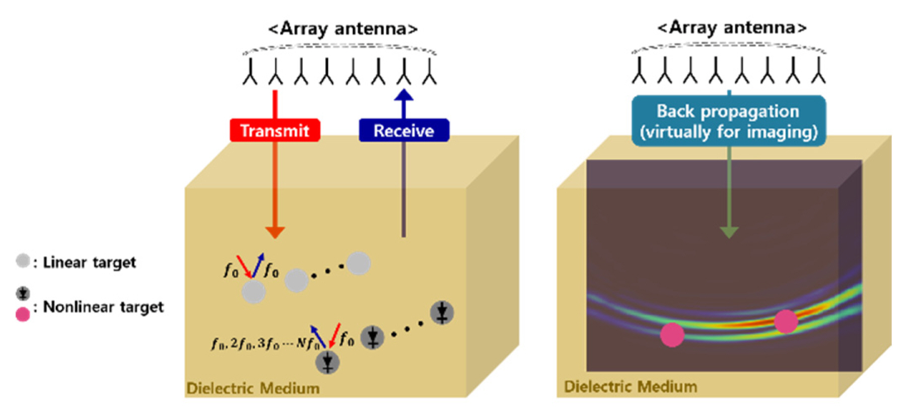
A general scenario of the proposed approach for the detection of buried nonlinear targets is illustrated in Fig. 1, where it is considered that both linear and nonlinear targets may exist in a buried environment. An antenna array is used to generate multistatic responses from the probed environment, which are then processed using DORT for the detection and focusing/imaging of the targets. Here, the antenna array can be configured into a monostatic array, where the same array is used to transmit (Tx) and receive (Rx) signals, or a bistatic array, where separate Tx and Rx arrays are used.
DORT is an array-based detection processing technique that separates detected targets and extracts information on their locatio’ns in terms of their eigenvalues and the corresponding eigenvectors through EVD [22]. In the case of an array with N elements, the time-domain monostatic/bistatic responses collectively make up an N×N multistatic matrix M(t). Each matrix element of M(t), namely mi,j(t), represents the response between the jth Tx and ith Rx antenna element pair. Therefore, in the presence of P scatterers, mi,j(t) can be expressed in terms of the scattered response from the pth scatterer, sp,j(t), and the Green’s function between the scatterer and the ith receive antenna, gi,p(t). This can be expressed as follows:
where * denotes convolution. To account for the responses from both linear and nonlinear targets, sp,j(t) can be expressed using a power series, as follows:
where f(t) is the transmit pulse and gp,j(t) represents the Green’s function between the pth scatter and jth Tx antenna. For linear targets, scattering only occurs in the fundamental band of f(t), which means that ck is nonzero only for k = 1. In contrast, in the case of nonlinear targets, the scattered responses contain the harmonic bands of f(t), resulting in nonzero ck for all values of k. Here, we are only interested in receiving the nonlinear responses in the second harmonic band, that is, only the portion of mi,j(t) corresponding to k = 2, namely
DORT processing can then be applied to Mh(ω), which refers to the frequency domain version of Mh(t). The time-reversal operator T(ω) can be defined as follows:
where † denotes the Hermitian conjugate corresponding to the time reversal in the frequency domain. The eigenvalues and eigenvectors can be extracted through EVD of T(ω) which can be expressed as:
where Λ(ω) is a diagonal matrix containing the eigenvalues λn and U(ω) is a unitary matrix containing the eigenvectors. Ideally, each nonzero eigenvalue should correspond to each detected nonlinear target, while the associated eigenvectors should represent the phase-conjugated Green’s functions between the array elements and target. This implies that the detected targets and their information can be separated in terms of their eigen-structure. The EVD of T(ω) can be done by means of the singular value decomposition of Mh(ω), since T(ω) is a Hermitian matrix [28].
Once the detected targets are separated by implementing EVD, a set of signals that can be backpropagated for selective focusing (imaging) of each target can be determined. Therefore, for the ith target, the backpropagation signals can be represented as follows:
where σn(ω) is the singular value (
In the following sections, the detection and location of buried nonlinear targets utilizing the aforementioned approach are demonstrated through numerical simulation and measurements.
III. Numerical Simulations and Measurements
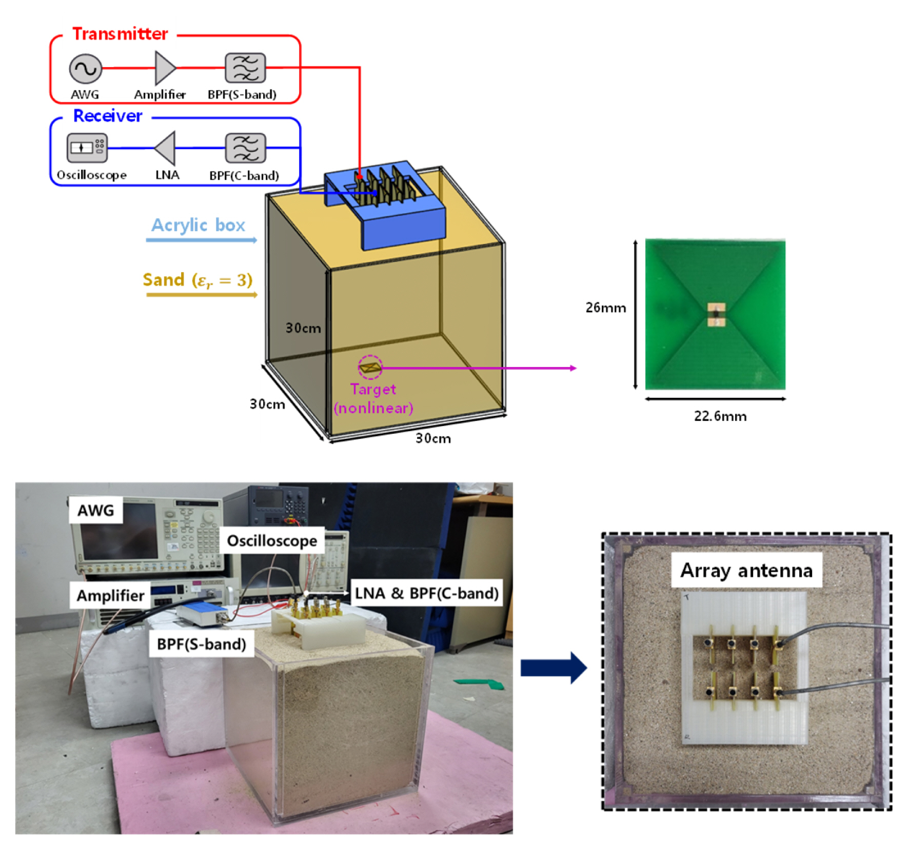
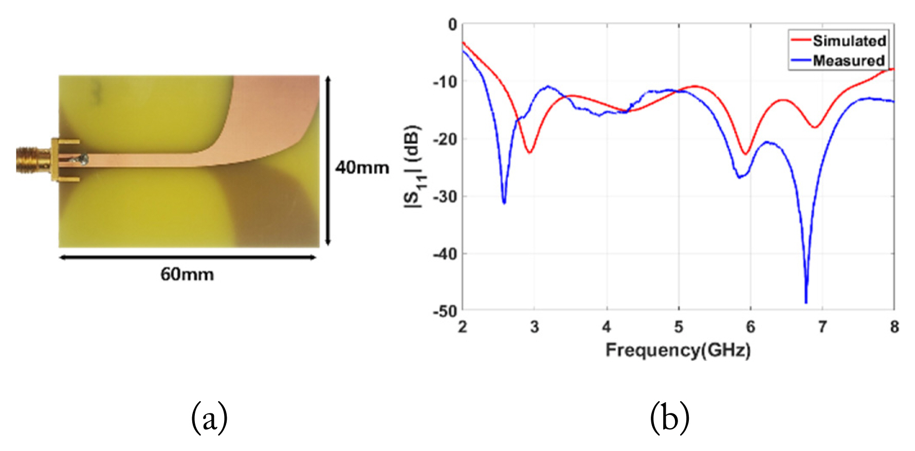
To validate the proposed approach, a buried nonlinear target detection environment was set up, as shown in Fig. 2, comprising an acrylic box (30 cm × 30 cm × 30 cm) filled with dry sand (ɛr = 3), and two separate antenna arrays for Tx and Rx. For the transmit signal, a Gaussian pulse with a center frequency of 3.1 GHz and a bandwidth of 200 MHz was used. The array elements were antipodal Vivaldi antennas (40 mm × 60 mm × 1.6 mm), as shown in Fig. 3(a). The reflection coefficient of the Vivaldi antenna is shown in Fig. 3(b), where the impedance bandwidth covers both the fundamental and second harmonic bands. The spacing of the array elements was set to 0.81λh, with λh being the wavelength at 6.2 GHz (2nd harmonic) in the sand. This spacing was determined by accounting for the transmit and receive frequencies—3.1 GHz and 6.2 GHz, respectively—as well as the potential presence of grating lobes and mutual coupling between the Tx and Rx arrays [28]. A planar bowtie structure (22.6 mm × 26 mm × 1.2 mm) was used to represent the linear and nonlinear targets, where a resistor and Schottky diode were used as their terminations, respectively. Since the purpose of this experiment was to demonstrate the feasibility of the proposed approach, a canonical shape, such as bowtie, that allows for sufficient scattering over a wide bandwidth, including the fundamental and second harmonic bands, was considered to be a good choice for the test target.
The performance of the proposed approach in the aforementioned test environment was examined by carrying out numerical simulation and measurements. The numerical simulation was performed using SEMCAD X [33]. The measurement setup is depicted in Fig. 2. On the Tx-end, a high-speed arbitrary waveform generator is used as the signal source, followed by a power amplifier. In addition, a band pass filter (3–3.2 GHz) is connected to suppress any self-generated harmonics occurring before transmitting through the Tx antenna. On the Rx-end, a band pass filter (5.6–7.0 GHz) is placed behind the Rx antenna, followed by a low noise amplifier to effectively amplify the received target harmonic responses for an oscilloscope to directly sample and capture them for signal processing. Measurements were performed for each Tx–Rx element pair to collect each
Fig. 4 illustrates three representative target configurations—Case 1 involves a single buried nonlinear target, Case 2 involves linear and nonlinear buried targets, and Case 3 involves two nonlinear buried targets.
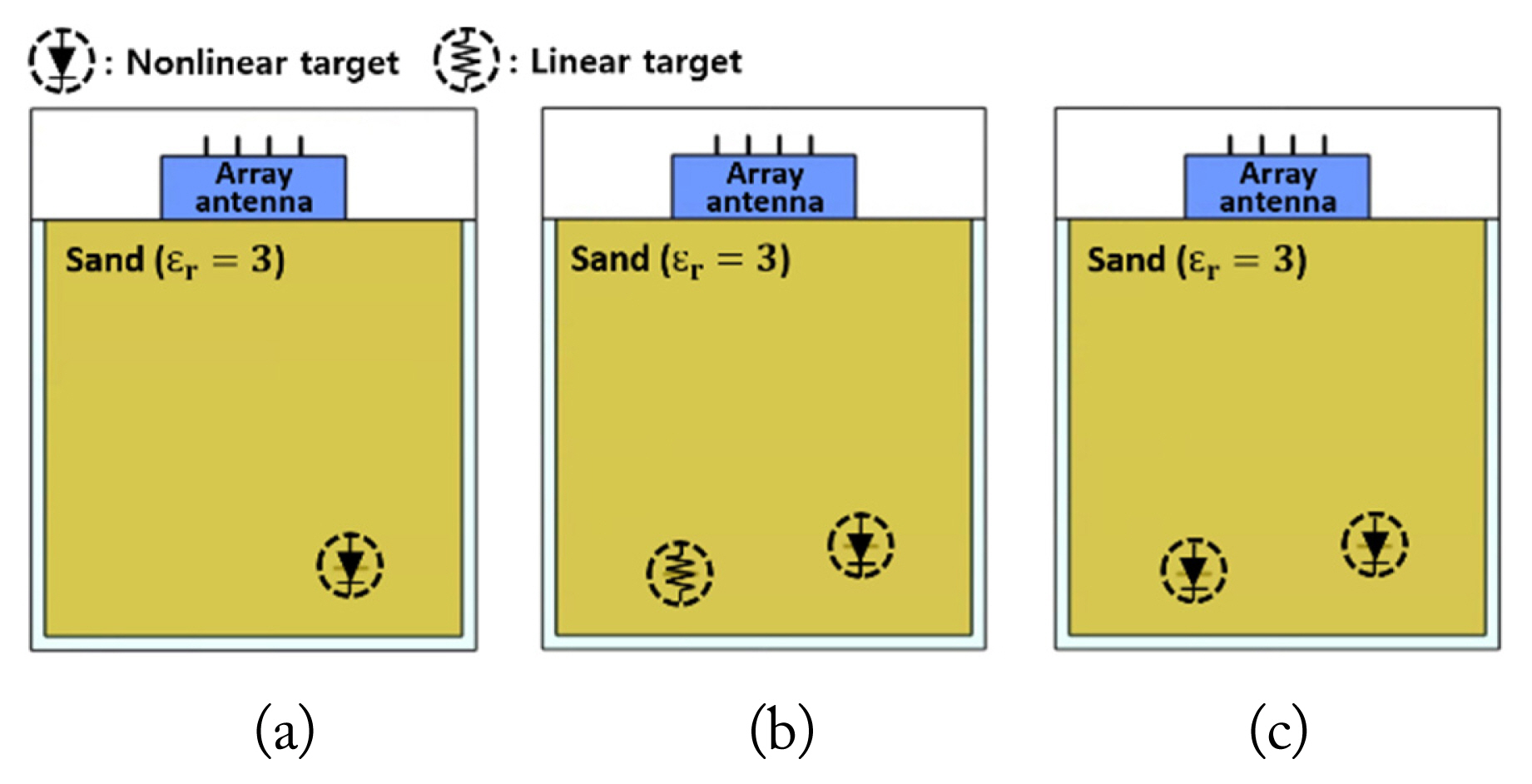
The three representative buried target cases tested: (a) Case 1, single nonlinear target, (b) Case 2, a nonlinear target and a linear target, and (c) Case 3, two nonlinear targets.
For Case 1, as shown in Fig. 4(a), a single nonlinear target was placed 25 cm below the surface, slightly to the right of the center. Based on the results of the DORT processing, the extracted eigenvalues from the simulated and measured data are shown in Fig. 5 and 5(b), respectively. The presence of the nonlinear target is confirmed by the dominant eigenvalue λ1(ω) in the second harmonic band, which can be verified in Fig. 5 for both the simulation and measurement. Fig. 6(a) and 6(b) show the imaging/ focusing results for the simulated and measured cases, respectively. The backpropagation signals are generated using v1(ω) and σ1(ω), based on Eq. (5). Note that the backpropagated waves are virtually generated using the numerical model in SEMCAD X for both cases. The images in Fig. 6 correspond to the time instance at which the backpropagated waves focus on the location of the nonlinear target, indicating that the nonlinear target is properly detected and located using the DORT processing.
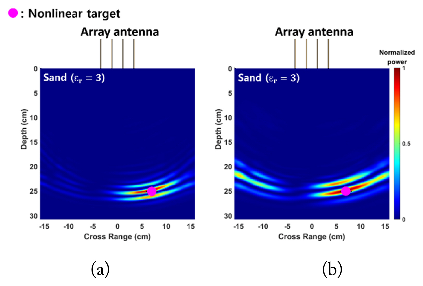
Backpropagation (imaging/focusing) results for the detected nonlinear target in Case 1 on using (a) the simulated and (b) measured data.
For Case 2, a nonlinear target was buried 25 cm below the surface, slightly to the right of the center, while a linear target was placed 23.5 cm below the surface, slightly to the left of the center. Fig. 7(a) and 7(b) show the extracted eigenvalues from the simulated and measured data, respectively. Even in the presence of the linear target, only one dominant eigenvalue could be extracted in the second harmonic band, indicating that only the nonlinear target was detected as a result of harmonic detection since the linear target did not generate any harmonics. The imaging/focusing results for the simulated and measured cases are shown in Fig. 8(a) and 8(b), respectively. It is evident that the nonlinear target is properly detected and located even in the presence of a linear target nearby.
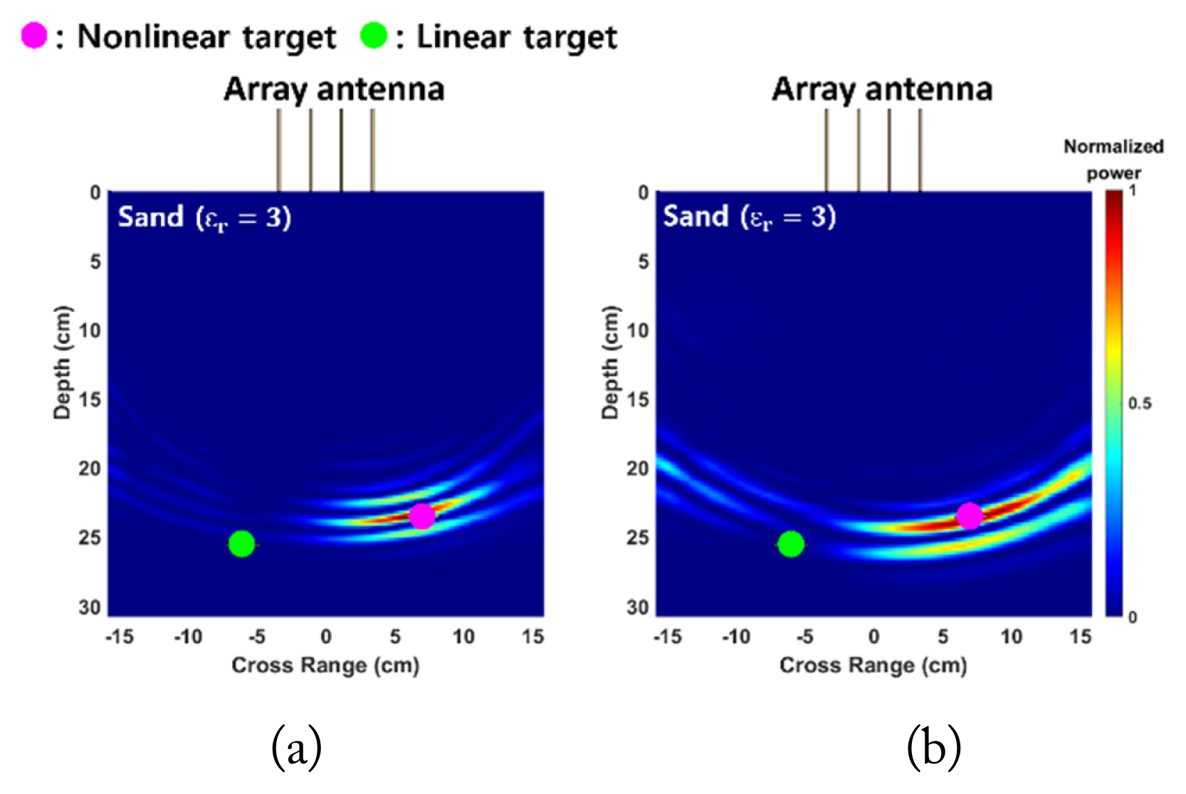
Backpropagation (imaging/focusing) results for the detected nonlinear target in Case 2 on using (a) the simulated and (b) measured data.
For Case 3, the same target locations as those in Case 2 were retained, but both targets were nonlinear targets. The extracted eigenvalues from the simulated and measured data are shown in Fig. 9(a) and 9(b), respectively. The presence of two nonlinear targets was confirmed by two significant eigenvalues, λ1(ω) and λ2(ω), appearing in the second harmonic band, indicating that both nonlinear targets were properly detected and separated in the eigenstructure. The backpropagation signals for each target were then generated using v1(ω) and v2(ω), as well as the corresponding σ1(ω) and σ2(ω). The selective focusing/imaging results of each nonlinear target are shown in Fig. 10. For each target, focusing of the backpropagated waves takes place at the target location, with the simulated and measured results in close agreement. This verifies that multiple buried nonlinear targets can be properly detected, separated and selectively located, using DORT.
IV. Effects of Target Orientation
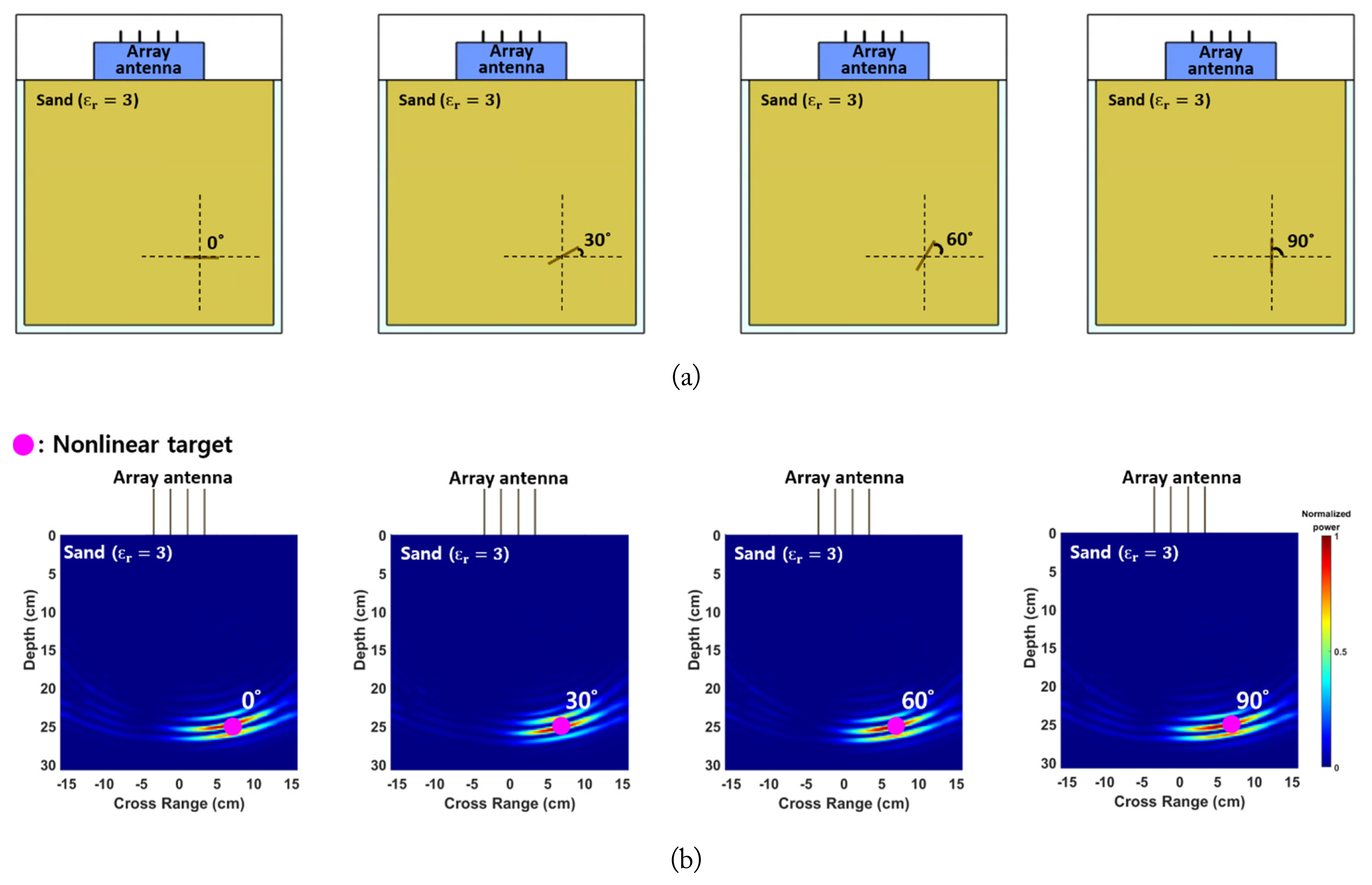
The simulated and measured results described in the previous section were obtained with the array antenna and the bowtie target facing each other directly. To test the effects of target orientation on detection performance, simulation was conducted by rotating the target about its center from 0° to 90°, as shown in Fig. 11(a). The imaging/focusing results for the four simulated cases, as shown in Fig. 11(b), highlight that the back-propagated waves remain properly focused on the location of the nonlinear target even when the array antenna and target do not face each other directly. This is primarily due to the bowtie structure exhibiting an omnidirectional pattern, which minimizes the influence of the target orientation. However, in practical scenarios in which realistic targets may be various electronic devices exhibiting more angle-dependent scattering patterns, a detailed analysis on the influence of target orientations would be important for accurately predicting the detection performance of the proposed approach.
V. Conclusion
This paper proposes and validates the application of harmonic detection and DORT processing for detecting buried nonlinear targets. Through simulation and measurements in a test environment, the detection and location of buried nonlinear targets were verified for various configurations, demonstrating the feasibility of the proposed approach for detecting buried small electronic devices, which are typically difficult to detect. The results of this study merit further investigation into the proposed technique, which holds good potential for application in areas where the detection of small buried nonlinear devices is crucial, such as security, military and biomedical applications.
Acknowledgments
This research was supported by the National Research Foundation (NRF) of Korea (Grant No. NRF 2020R1F1A1072238).
References
Biography

Young Jin Song, https://orcid.org/0009-0008-7330-8483 received his B.S. degree in electronic engineering from Soongsil University, Seoul, South Korea, in 2022, and is currently pursuing his combined M.S./Ph.D. degree in electronic engineering at Soongsil University. His research interests include nonlinear radars and wireless power transfer.

Sun K. Hong, https://orcid.org/0000-0002-3794-3171 received his B.S. degree in electrical engineering from the University of Maryland, College Park, MD, USA, in 2005, and his M.S. and Ph.D. degrees in electrical engineering from Virginia Tech, Blacksburg, VA, USA, in 2008 and 2012, respectively. From 2005 to 2015, he was a research engineer with the U.S. Naval Research Laboratory, Washington, DC, USA, where he was involved in research related to time-domain techniques in electromagnetics, nonlinear electromagnetic interaction, radars, electro-magnetic scattering, high power microwave (HPM) applications, and antennas. From 2015 to 2017, he was an assistant professor in the Department of Electrical and Computer Engineering, Rose-Hulman Institute of Technology, Terre Haute, IN, USA. Since 2017, he has been with Soongsil University, Seoul, South Korea, where he is currently an associate professor at the School of Electronic Engineering. His current research interests include wave-front control techniques, wireless power transfer, EM waves in complex propagation environments, detection of nonlinear devices, radars, high-power electromagnetics, and antennas.

