I. Introduction
In the field of electronic warfare, the use of various array antenna systems capable of beamforming over a wide bandwidth using high-power radiation has been gradually increasing [1ŌĆō3]. Such systems are often necessary in critical electronic warfare systems, such as high-power jammers, long-range radars, and target direction-finding systems, which play key roles in establishing a superior electromagnetic spectrum environment [4ŌĆō6]. For example, broadband jammers used in avionics warfare typically operate within the frequency range of 1ŌĆō18 GHz, while long-range radars used in ground stations function within the 2ŌĆō4 GHz range [7]. Furthermore, direction-finding systems for detecting unauthorized transmitters often operate in the 1ŌĆō40 GHz range. Since these high-power broadband systems are usually mounted on an aircraft, vehicle, or ground base station, which offers limited mounting space, a small-sized array antenna that satisfies wide bandwidth operations is required. Various types of broadband antennas, such as a ridged horn, an antipodal Vivaldi, and a log periodic dipole array (LPDA), have been extensively studied for use in these systems [8, 9]. Furthermore, in terms of power efficiency, an array antenna system that can form various shapes of beam patterns by adjusting the magnitude and phase of individual antenna elements is crucial [5, 10ŌĆō15]. Therefore, beam synthesis studies have been conducted primarily for wireless communication and wireless power transmission applications [16, 17]. Recently, it has been applied to specific electronic warfare situations. For example, a flat-top beam can be used to uniformly transmit signals to a number of systems, cosecant-squared beams can be employed for air-to-ground scanning, and an iso-flux beam can be used at high altitudes to transmit uniform power to the ground. However, most studies have yielded only theoretical beam synthesis results, assuming that the array elements are ideal isotropic sources. In actual array antennas, each antenna element has different radiation patterns with mutual couplings. As a result, unexpected performance degradations, such as phase changes in antenna ports, reduction of radiation gain, and distortion in the radiation pattern, are observed in many cases. These problems also lead to distorted or unintended results pertaining to synthesized array beam shapes. Therefore, it is necessary to identify and study methods that can help obtain various beam shapes for specific purposes by accounting for the different radiation patterns and mutual couplings of each array element.
In this paper, various array beam shapes for high-power electronic warfare applications are derived using an actual broadband array antenna. For high-power arrays to be applied in a limited mounting space, a compact printed LPDA operating over a wide bandwidth is designed. To confirm the broadband characteristics of the designed antenna, the LPDA is fabricated, and its antenna performances, such as reflection coefficients and radiation patterns, are measured in a full anechoic chamber. The LPDA is then extended to an 8 ├Ś 1 array, and the active element patterns (AEPs) of the individual elements, considering their mutual couplings, are obtained by conducting measurements as well as simulations. Following this, after adjusting the weights of each AEP, beam synthesis within the guided mask is performed by the superposition of several array patterns with different steering angles and amplitudes. To derive synthesized array beam shapes that closely resemble the guided mask, the Taylor window weighting method is applied to each array pattern. Finally, beam synthesis for a flat-top beam, a cosecant-squared beam, and an iso-flux beam is performed using the Taylor window-weighted AEPs. The results are then compared with those of the beam shapes using ideal isotropic patterns, ultimately demonstrating that various beam shapes for high-power electronic warfare, such as the flat-top beam, the cosecant-squared beam, and the iso-flux beam, can be achieved using the AEPs of the actual array antenna.
II. Design and Measurement of the Broadband LPDA and its Array
1. Broadband LDPA
Fig. 1 presents the geometry of the proposed compact LPDA for high-power broadband beamforming applications. The LPDA element was optimized to satisfy broadband characteristics operating within the 2ŌĆō5 GHz range and boresight gain of more than 3 dBi for high-power beamforming systems, which typically allow limited antenna mounting space. The optimized antenna was printed on an FR-4 substrate (╔ør = 4.3, tan╬┤ = 0.018) to minimize the dimensions of length ls, width ws, and thickness ts, as shown in Fig. 1(a)ŌĆō1(c). In the LPDA design, a total of 13 dipole elements were employed to realize high directivity and broadband characteristics, which would help attain the various beam shapes required in electronic warfare systems. Each dipole element was designed considering a geometric ratio Žä and an apex angle ╬▒, as expressed using equations as follows:
As shown in Fig. 1(a) and 1(b), the geometric parameters of length la1 and width wa1 of the longest element determined the lowest operating frequency to be 2 GHz. Subsequently, the other elements were sequentially designed with regard to the geometric ratio Žä. Notably, lan refers to the length of the nth dipole element, while the length of the (n+1)th element can be given by Žä┬Ęlan. The position parameter Xn was then calculated in the same way. Meanwhile, the length la13 and width wa13 at position X13 were designed to cover the highest operating frequency of 5 GHz. Furthermore, the relation between the length lan and location Xn of the dipoles was determined by the apex angle ╬▒ in Fig. 1(b). The boom located at the center of the substrate was designed to feed the dipole elements with a width of wb and length of ls. Notably, the dimensions of an LPDA, as determined by the two design factors (Žä an d ╬▒), have a significant impact on broadband impedance-matching characteristics. The optimized design parameters, the detailed values of which are listed in Table 1, were obtained using the CST Studio Suite EM simulation software (http://www.cst.com). The single LPDA element was then extended to an 8 ├Ś 1 linear array configuration, maintaining array spacing of ╬╗/2 at 4 GHz to synthesize various beams for electronic warfare purposes, as shown in Fig. 1(d). It is quite obvious that array antennas equipped with a large number of elements have an advantage in beam synthesis due to the narrow half-power beam width (HPBW) of the array pattern [18ŌĆō21]. However, there are some disadvantages as wellŌĆöthe array system should be bulky and heavy. To compensate for these disadvantages, this study derived the beam synthesis performance using only eight elements of the LPDA that exhibited high gain and broadband characteristics.
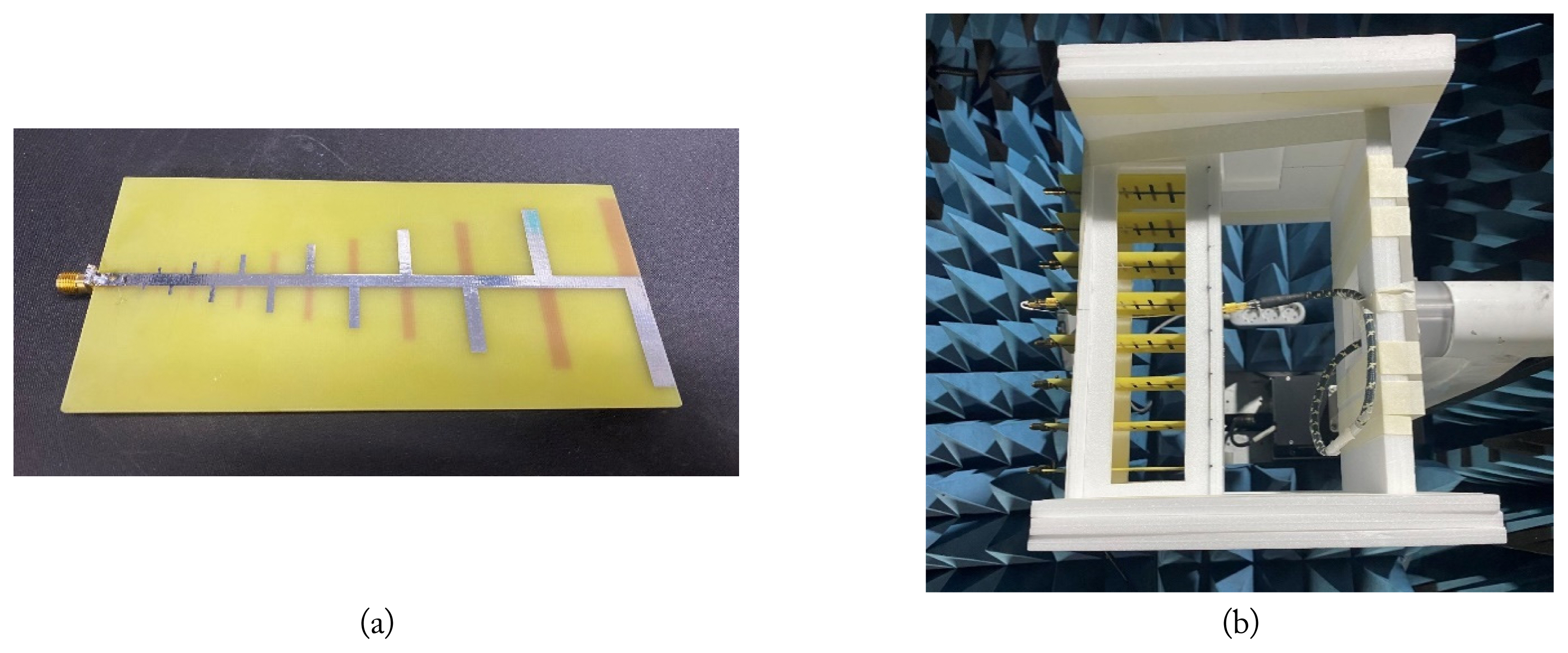
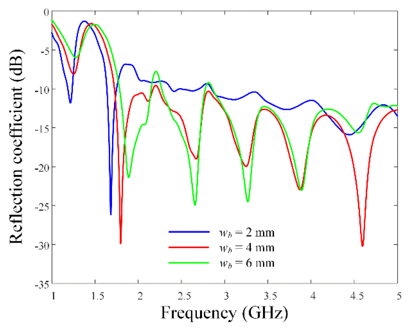
Fig. 2(a) presents a photograph of the fabricated single LPDA, which shows that the proposed antenna is directly fed by an SMA connector at the top of the boom. Fig. 2(b) illustrates the extended 8 ├Ś 1 array in the x-axis, along with the proposed LPDA. The eight array elements were fixed at exact positions by a multi-layered, lightweight Styrofoam jig. Fig. 3 presents the reflection coefficients with regard to the LPDA boom width wb. It is observed that when wb is 4 mm, the reflection is less than ŌłÆ10 dB in the 1.7ŌĆō5 GHz range.
2. LDPA Array
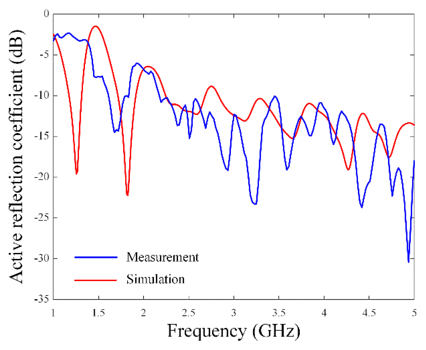
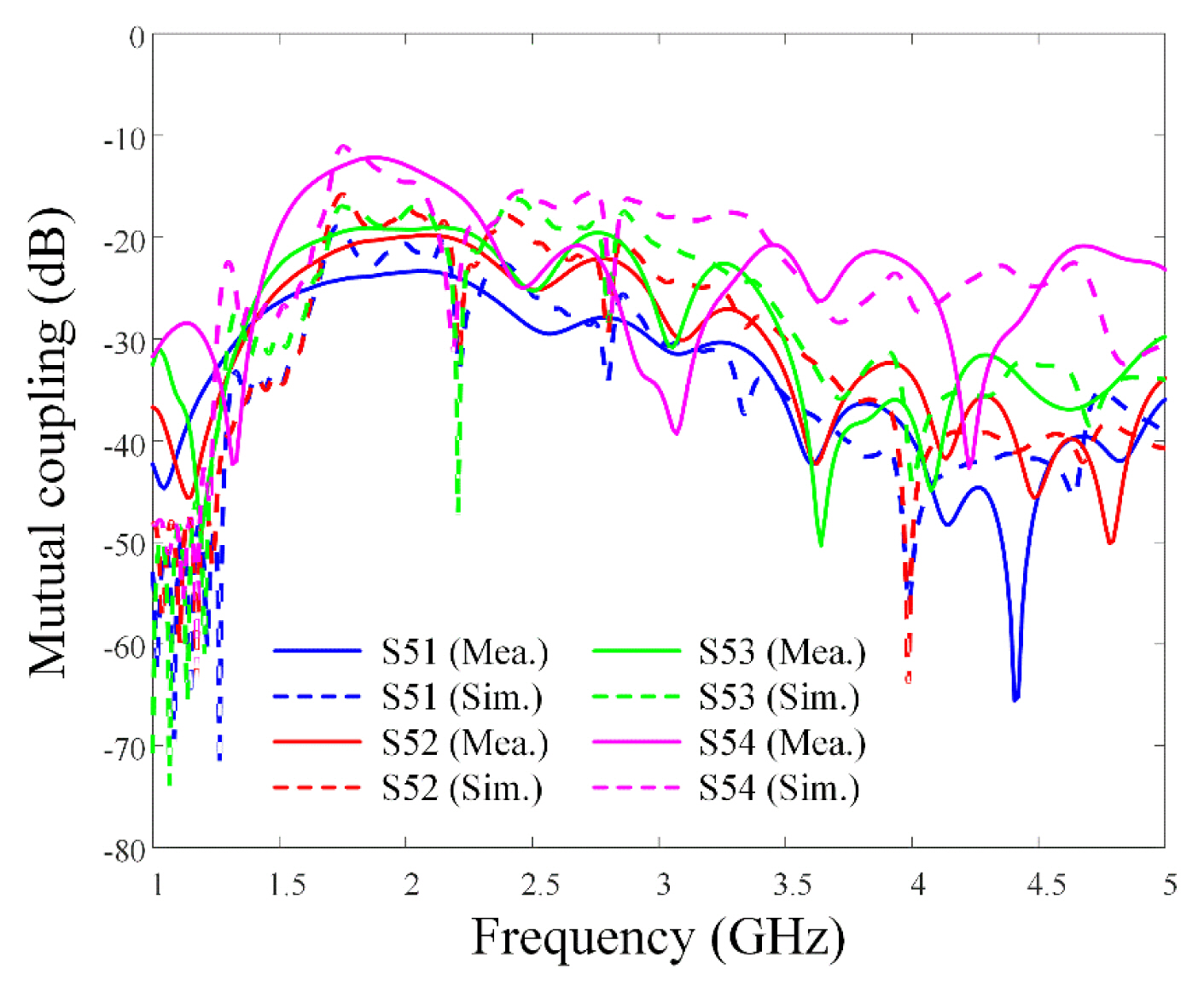
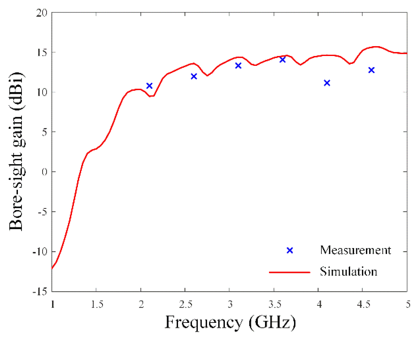
Fig. 4 presents the measured and simulated active reflection coefficients (ARCs) of Ant5 (the center element) of the proposed compact printed LPDA array. The measured ARCs show broadband characteristics of less than ŌłÆ10 dB within the 2.2ŌĆō5 GHz range (fractional bandwidth of 93.3%), which agrees well with the simulation results. Furthermore, although a slight change in the reflection coefficient was observed due to mutual coupling changes when using the array antenna for the various beam synthesis estimations, no significant change could be identified. Therefore, the designed LPDA can be employed for high-power beamforming in electronic warfare systems with a wide bandwidth. Fig. 5 shows the results of mutual coupling between Ant5 and the other elements. Furthermore, mutual couplings with Ant1, Ant2, Ant3, and Ant4 were measured. Notably, the mutual coupling with Ant4 (the nearest element) was less than ŌłÆ10 dB between 1 GHz and 5 GHz. Fig. 6 presents the measured and simulated boresight gains of the 8 ├Ś 1 array antenna. The solid line indicates the simulation results, while the ŌĆ£├ŚŌĆØ markers represent the measurement results. It is observed that the measured boresight gains are more than 10 dBi from 2 GHz, with the simulation results showing a similar tendency. Fig. 7(a)ŌĆō7(f) present the measured and simulated 2D AEPs of Ant2 and Ant5 at 2.5 GHz, 3.5 GHz, and 4.5 GHz, respectively. As expected, Ant2, which is located near the edge, has an asymmetric radiation pattern, while Ant5, located at the center, has a symmetrical beam pattern. At 4.5 GHz, Ant2 has a maximum gain of 6.3 dBi (╬Ė = ŌłÆ56┬░), and Ant5 shows 6.0 dBi (╬Ė = ŌłÆ22┬░). However, since significant distortion is often observed in the patterns of individual elements in actual array antennas, it is necessary to use AEP instead of the ideal isotropic radiation pattern for beam synthesis.
III. Beam Synthesis using the Broadband LPDA
Beam synthesis can be conducted through the superposition of several array patterns bmf(╬Ė,╬Ėm) with different steering angles ╬Ėm and amplitudes bm, as shown in a equation as follow [12]:
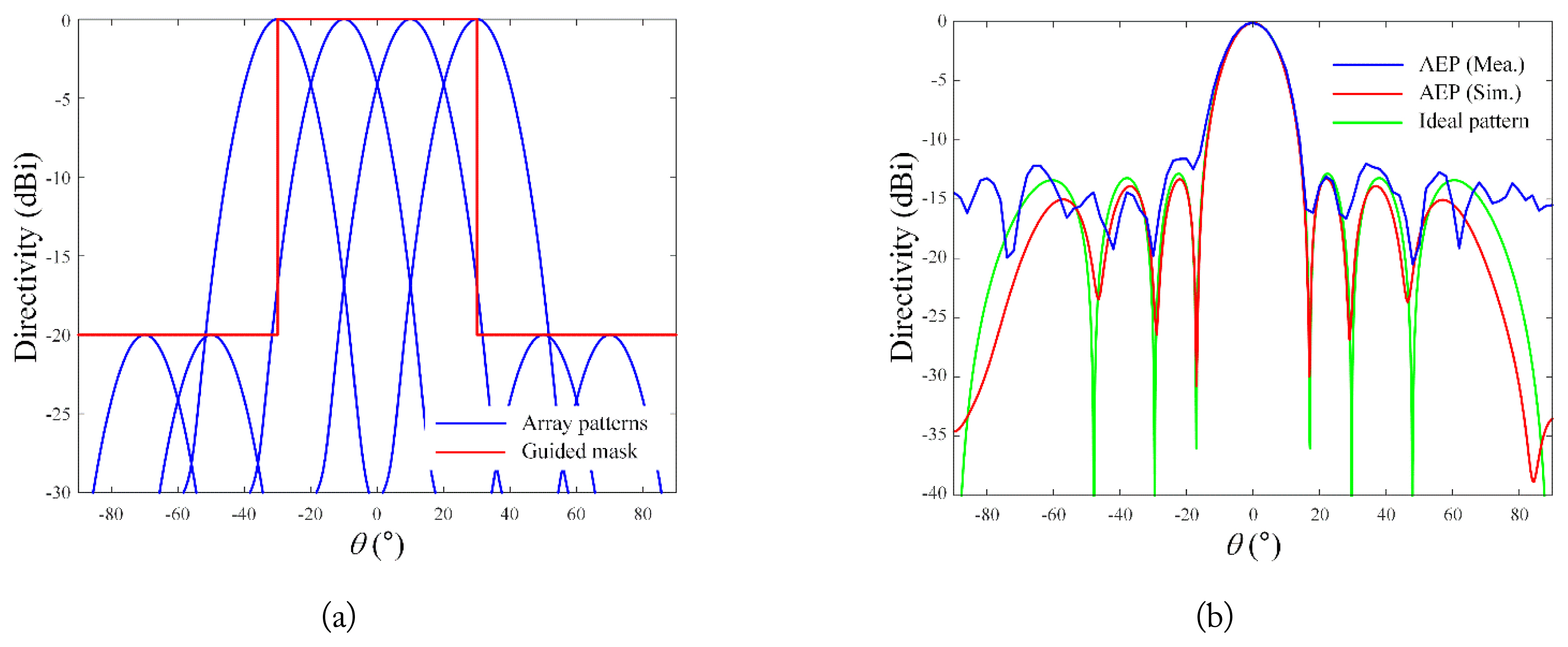
Here, bm is the required amplitude weighting, and ╬Ėm is the steering angle for each array pattern. For example, when a guide mask for the desired beam shape is defined in Fig. 8(a), the most appropriate beam pattern can be obtained by the superposition of multiple array patterns. Notably, to derive a synthesized beam shape that closely resembles the guided mask, a narrow HPBW and a low sidelobe level (SLL) is required for each array pattern. Therefore, the Taylor window weighting method is applied to each array pattern to achieve a low SLL using an equation as follow:
Here, an represents the weighted amplitude applied to the nth element in the Taylor window, and gn(╬Ė,╬Ėm) denotes the AEP of the nth element with steering angle ╬Ėm. The array patterns for the designed 8 ├Ś 1 array when using Taylor window weighting are shown in Fig. 8(b). The resulting measurements using AEPs exhibited an HPBW of 17.4┬░ and an SLL of 19.4 dB.
Following this, beam synthesis for the flat-top beam, cosecant-squared beam, and iso-flux beam were carried out using Taylor window-weighted array patterns. Notably, the root-mean-square error (RMSE) lies within the range of 0 and 1, meaning that an RMSE of 0.2 indicates an error of 20%, which can be evaluated as a relatively small error. The RMSE was calculated as an evaluation metric to observe the similarity of the beam pattern shape between the measurement results and the guided mask. This can be obtained using an equation as follow:
Here, F(╬Ė) represents the normalized directivity of the synthesized beam, and G(╬Ė) is the value of the guided mask at angle ╬Ė. Notably, since there are 91 sampling points (L) between ŌłÆ90┬░ and 90┬░, the synthesized beam and the guided mask were compared by examining 91 uniformly distributed points between ŌłÆ90┬░ to 90┬░.
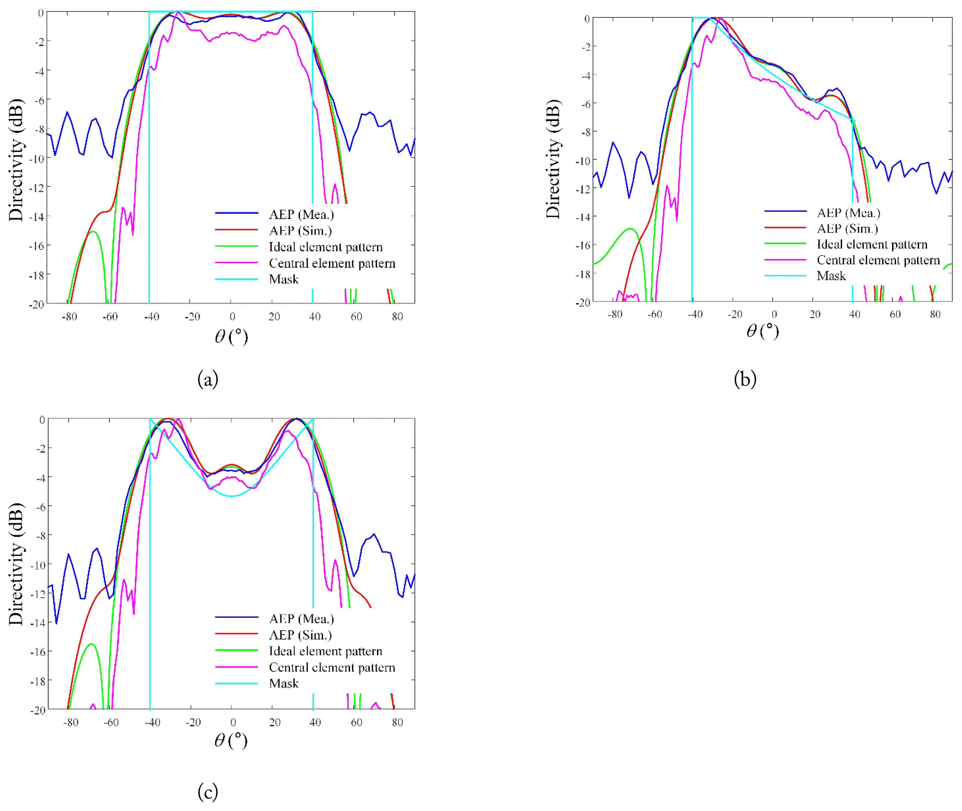
Fig. 9(a) depicts the synthesized flat-top beams, which are generally used for searching and detecting targets at wide scan angles. The goals of the flat-top beam were to achieve a beamwidth of 80┬░ (ŌłÆ40 Ōēż ╬Ė Ōēż 40┬░ and an SLL of more than 10 dB. Beam synthesis was performed by determining the amplitude bm when the number of array patterns M was 30. When using the measured AEPs, the results showed a beamwidth of 75┬░ and an RMSE of 0.159 compared to the guided mask.
Fig. 9(b) illustrates the cosecant-squared beam, which is typically used for high-power airborne jamming systems. Similar to the method described previously, the cosecant-squared beam was obtained based on the guided mask (cosec2(11.2┬░) at ŌłÆ40┬░ Ōēż ╬Ė Ōēż ŌłÆ31.6┬░ and cosec2(╬Ė+40┬░) at ŌłÆ31.6┬░ Ōēż ╬Ė Ōēż 40┬░), resulting in the optimum bm (M = 30) for the most appropriate synthesized beam. The cosecant-squared beam was set to maintain a difference of 7.27 dB between the maximum and minimum values within 80┬░ of the beamwidth. The results of the cosecant-squared beam showed that the shape attained a maximum directivity of 0 dB at ╬Ė = ŌłÆ30┬░ and a reduced directivity of ŌłÆ7.55 dB at ╬Ė = 40┬░, thus achieving an RMSE of 0.167 compared to the guided mask.
Fig. 9(c) presents the results of the iso-flux beam, which is generally used in the earth-observing missions of satellites. Similar to the previous beams, the iso-flux beam was also obtained based on the guided mask (1.5├Ś10ŌłÆ3╬Ė2+1 at ŌłÆ40┬░ Ōēż ╬Ė Ōēż 40┬░). Its beamwidth was set to 80┬░ and gain difference was set to 5.4 dB. When using the measured AEPs, the iso-flux beam exhibited right-side peak directivity at ╬Ė = 32┬░ and left-side peak at ╬Ė = ŌłÆ32┬░. In the boresight direction (╬Ė = 0┬░), a low directivity of ŌłÆ3.57 dB was observed, and an RMSE of 0.162 was obtained compared to the guided mask.
This study used a different number of M based on the shape of the synthesized beam. Notably, an inadequate number of M results in multiple nulls in the synthesized beam, whereas an excessive number of M increases the SLL of the beam. Therefore, an appropriate value of M should be used to derive the beam that best resembles the shape of the mask. The results of this study confirm that various beam shapes for high-power electronic warfare applications can be achieved using the AEPs of the designed LPDA. To compare the similarities between the measurement and simulation results, the RMSEs obtained with regard to the guided masks are listed in Table 2. It is evident that the measurement results of the synthesized beams are similar to the simulation results at ŌłÆ40┬░ Ōēż ╬Ė Ōēż 40┬░, as indicated by the low RMSEs. However, a relatively high difference was observed in the case of SLLs. These differences may be attributed to the fact that measurement results usually show degraded performance compared to theoretical simulation results due to various reasons, such as measurement conditions, fabrication errors, and cable loss [22, 23]. In particular, since SLLs are more sensitive to errors, they exhibit greater degradation. Moreover, the performance degradation observed in the measurement can occur when the fabricated antenna is applied to the system. Therefore, when conducting beam synthesis research, it is crucial to confirm performance through fabrication.
IV. Conclusion
In this paper, various beam shapes for high-power electronic warfare applications were derived using an actual broadband array antenna. Specifically, a compact printed LPDA with broadband characteristics was fabricated and measured for use in a limited mounting space. Subsequently, the LPDA was extended to an 8 ├Ś 1 linear array, while AEPs were obtained through measurement and simulation. The measured ARC was less than ŌłÆ10 dB within the 2.2ŌĆō5 GHz band, while the measured boresight gains were more than 10 dBi from 2 GHz. Furthermore, beam synthesis was performed by the superposition of several array patterns with different steering angles and amplitudes. The flat-top beam achieved a beamwidth of 75┬░ and an RMSE of 0.159. The cosecant-squared beam, which attained maximum directivity at ╬Ė = ŌłÆ30┬░ and a reduced directivity of ŌłÆ7.55 dB at 40┬░ achieved an RMSE of 0.167 compared to the guided mask. In addition, the iso-flux beam obtained an RMSE of 0.162 compared to the guided mask. These results were compared with those of the beam shapes obtained using ideal isotropic patterns, which ultimately confirmed that various beam shapes can be achieved in high-power electronic warfare applications using the actual array antenna.