Design of Magnetic Coupling Mechanism with Different Primary and Secondary Coils for Maximum Output Power
Article information

Abstract
Output power is an important performance metric related to static or quasi-static wireless power transfer (WPT). As an important component of WPT, the electrical parameters of a magnetic coupling mechanism (MCM) are directly related to its output characteristics. Notably, an optimal WPT design is largely based on MCMs using the same primary and secondary coils. However, in some scenarios involving limited space, the physical structure and electrical parameters of the coils cannot be kept completely consistent. Based on the influence of physical parameters on coupling performance and system characteristics, an optimal design method for MCMs using different primary and secondary coils to ensure maximum output power is proposed. The best receiving coil within a limited space that achieves maximum power at a specific location was selected. Experiments were conducted, with the corresponding results verifying the correctness of theoretical and simulation analyses, as well as the effectiveness of the proposed method.
I. Introduction
The continuous consumption of fossil fuels has made environmental problems, such as global warming, increasingly prominent. To address these circumstances, replacing petrol vehicles with electric vehicles (EVs) has become a strategic policy adopted by many countries [1–4]. Driven by the promotion of policies and incentives, the number of EVs has sharply increased. However, the widespread applications of EVs require proper solutions to their charging problems. Charging stations are the most common power replenishment equipment for EVs. However, manual operations are required in the charging process, posing risks pertaining to poor contact and electric shock on rainy days, among others [5, 6].
Wireless power transfer (WPT) offers a new solution for charging EVs [7, 8]. In WPT, the electromagnetic field is used as the medium for non-contact power transmission, thus eliminating safety issues such as sparks and electric shock. Combined with intelligent identification and control, manual operation during EV charging can be entirely eliminated [9, 10] and completely unmanned operations can be achieved. The modular structure of WPT allows for embedded installations that do not require additional land, which is extremely beneficial for urban planning. WPT offers numerous advantages in the field of EV charging and, therefore, has received increasing attention in recent years [11, 12].
Extensive research and exploration has been conducted on WPT for EVs, mainly with regard to the converter and magnetic coupling mechanism (MCM) [13–15]. Converter technology is relatively mature, with a general efficiency higher than 95% or even 98% [16, 17]. The design of MCM can be divided into two parts—the compensation topology and the coil structure [18, 19]. The three most common forms of compensation topologies are series and parallel compensation, which are the basic compensation topologies [20, 21], and LCC compensation, which is representative of a new compensation topology for meeting specific performance demands [14, 22]. Furthermore, a unipolar Q-type coil is the most widely used structure prevalent in MCMs [23, 24]. However, to meet the high power requirements at close distance for EVs, the use of DD-type coil has been proposed [25, 26], since it comprises two-directional magnetic fields on one side, due to which it is also known as the bipolar coil.
In published research on WPT for EV charging, the optimization of transmission performance and structural parameters has usually been based on the identical structure of the MCM, which uses the same primary and secondary coils. However, in practical applications, EV wireless charging can be significantly affected by the characteristics of WPT and the application environment. For instance:
1) Placing the transmitter on the ground in EV wireless charging makes it easy to achieve a unified design, but the volume of the EV receiver may be limited.
2) The ground clearance of different EVs varies. Therefore, diverse kinds of EVs need to be optimized and designed under various transmission distances to achieve better performance.
3) Different batteries have varying characteristics. Therefore, to determine the optimal receiver, EV wireless charging needs to be adjusted according to the properties of the batteries.
Compared to fuel-based vehicles, EVs are at a disadvantage with regard to their power replenishment time. Addressing this issue would require greater output power from WPT to shorten the charging time [4, 11, 27]. Therefore, to build a unified transmitter, a targeted design should be developed for receivers of different EVs to achieve maximum power. The traditional optimal method for achieving maximum output power using the same coils is no longer applicable. Therefore, in this study, a design method for the MCM that employs heterogeneous primary and secondary coils is proposed. The size of the receiving coil, the transmission distance, and the load differences are comprehensively examined to achieve maximum output power at a fixed distance within a limited design space.
II. Theoretical Analysis
1. Transmission Performance of WPT
In an LC resonant circuit, the frequency f of voltage and current are not affected by the ideal resonant frequency

Equivalent circuit of WPT with SS compensation topology.
where current İt and İr of the primary and second sides, respectively, can be formulated as follows:
where
Furthermore, the input power Pin, output power Pout, and transmission efficiency η can be expressed as follows:
where Us and Ir are the modulus values of U̇S and İr.
Based on Eq. (5), the variation in transmission performance with regard to mutual inductance was obtained, as shown in Fig. 2. It is noted that the larger the mutual inductance reactance XM, the higher the transmission efficiency η. In other words, an increasing mutual inductance M or resonant frequency f can improve η. Furthermore, when output power Pout attains its maximum value, XM must satisfy the following equation:

Relationship between transmission performance and mutual inductance.
where
Moreover, for WPT with determined physical parameters, a unique value of mutual inductance M that maximizes the output power is usually considered. The maximum output is
When the primary and secondary sides of the MCM have the same resonant frequency, which is the same as that of the source, the ideal resonant state is achieved, Xt =Xr =0. Therefore, Eqs. (6) and (7) can be simplified as follows:
2. Maximum Output Power of the MCM
For an MCM characterized by different primary and secondary coils, the most significant electrical parameter characteristics are the unequal inductances L1 and L2. To meet resonance conditions, it may be assumed that the compensating capacitances and inductances satisfy L1C1=L2C2. On determining the structural parameters of the transmitting coil and the resonance frequency f, Eqs. (6) and (7) indicate that the maximum output power is restricted by the secondary impedance Xr and the mutual inductance reactance XM.
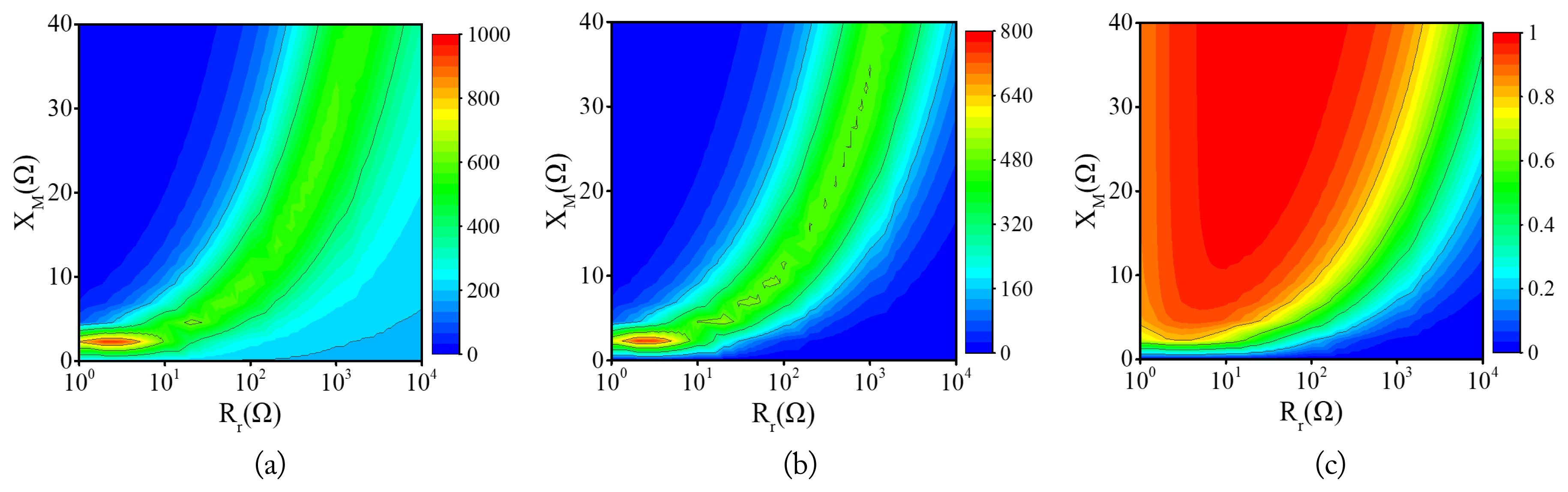
Notably, when the frequency fsource of the source is equal to the ideal resonant frequency f0, Xt =Xr =0 and Zt=Rt, Zr =Rr. Fig. 3 shows the impact of mutual inductance reactance XM and receiver resistance Rr on the performance of equivalent circuit, where Rr is positively correlated and XM is negatively correlated with input power Pin. Furthermore, when either Rr or XM is kept constant, the output power Pout will initially increase and then decrease with an increase Rr or XM. As for the transmission efficiency η, as shown in Fig. 3(c), it increases continuously with an increase in XM or a decrease in Rr, indicating an opposite trend as that of Pin.

Influence of mutual inductance reactance XM and receiver resistance Rr on performance under ideal resonant conditions: (a) input power Pin, (b) output power Pout, and (c) transmission efficiency η.
If the frequency fsource of the source is not equal to the ideal resonant frequency f0, Xt/L1=Xr/L2 ≈ 0. Assuming fsource =f0 + Δf, the receiver impedance Zr cannot be considered purely resistive. Fig. 4 depicts the impact of mutual inductance reactance XM and receiver resistance Rr on the performance of WPT under non-ideal resonant conditions. Notably, the variation trend of the output power Pout and transmission efficiency η is the same as that shown in Fig. 3(b) and 3(c). However, the maximum output power Pout·max is reduced. This indicates that the power difference in Pout·max is related to the frequency difference Δf—the greater the Δf, the greater the reduction in Pout·max. Furthermore, the input power Pin in Fig. 4(a) is different from that in Fig. 3(a). This variation is the same as that of Pout under non-ideal resonant conditions—increasing initially to then decrease with an increase in XM or Rr.
Influence of mutual inductance reactance XM and receiver resistance Rr on performance under non-ideal resonant conditions: (a) input power Pin, (b) output power Pout, and (c) transmission efficiency η.
Based on the output power estimations shown in Figs. 3 and 4, a unique mutual inductance reactance XM is observed, which achieves the maximum output power Pout·max for any receiver impedance Zr, thus satisfying Eq. (6). Furthermore, XM = ωM is influenced by mutual inductance M and angular frequency ω. The primary and secondary impedances—Zt = Rt + jωLt + 1/jωCt and Zr = Rr + jωLr + 1/jωCr —are influenced by coil resistances RAC, self-inductances L, and angular frequency ω. Moreover, M, RAC, and L are found to be closely related to the physical parameters and the relative spatial position of the coils. Notably, during static WPT, the relative spatial position of the coils usually remains constant. This paper takes advantage of the effects of the physical parameters of coils on their electrical characteristics to optimize their structure and maximize their output power.
III. Electrical Parameters of the MCM
For the MCMs used for EVs, electromagnetic shielding is usually implemented to reduce electromagnetic leakage and improve transmission performance, as shown in Fig. 5(a). Notably, the influence of electromagnetic shielding on the electrical parameters of coils does not change the impact of its physical parameters on self-inductance or mutual inductance [28, 29]. In other words, the difference in electrical parameters between two typical MCMs, as shown in Fig. 5, is mainly reflected in the relative magnetic permeability μ. To simplify the analysis process, this study considers an MCM without electromagnetic shielding, as shown in Fig. 5(b), as an example.
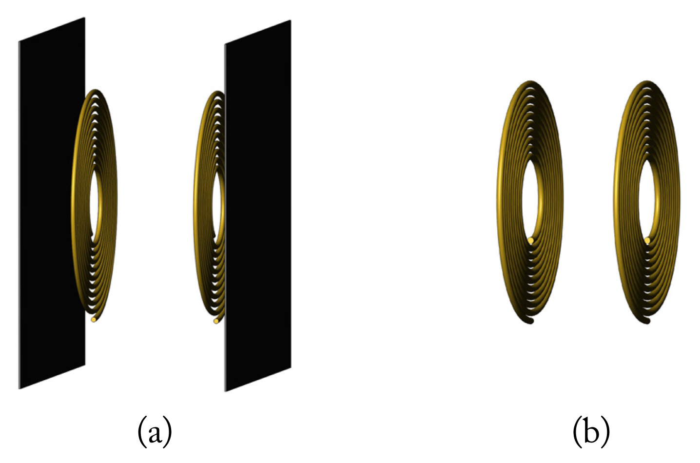
A typical MCM with two coils: (a) with electromagnetic shielding and (b) without electromagnetic shielding.
To achieve maximum output power within a limited design space, appropriate parameters and structure of the MCM need to be selected and optimized based on the application scenario. Therefore, the mutual inductance and impedance were adjusted to satisfy Eq. (6). For a typical MCM without electromagnetic shielding, as depicted in Fig. 6, the optimization of its physical parameters involves (i) both its transmitting and receiving coils, and (ii) either the transmitting or receiving coil. In the case of EV wireless charging, the transmitting coil can be flexibly designed, but the receiving coil is limited by the size of the EV chassis, which indicates that Situation (ii) applies in this particular context. Therefore, the current paper selected this situation as an example for optimizing the MCM. Subsequently, the transmitting coil and the relative spatial position were fixed, while the receiving coil was designed within a limited space to obtain the maximum output power.

A typical MCM without electromagnetic shielding.
1. Mutual Inductance
Mutual inductance refers to the ratio of the magnetic flux linking any coil to the current-producing magnetic flux in the other coil. For two parallel single-turn circular coils [30], the mutual inductance can be expressed as follows:
where
Notably, a multi-turn coil can be considered equivalent to some single-turn coils with a continuously varying radius. Furthermore, since the coil radius RC is usually much larger than the wire radius r, the effect of r can be ignored. Therefore, the equivalent radius of the ith single-turn coil from the center can be formulated as RCi ≈ RC0+(i−1)d, where d is the pitch. Notably, all single-turn coils have the same center. Furthermore, the distance Dt,r between the center of the transmitting coil and the receiving coil also remains constant. Assuming that the turns of the transmitting and receiving coils are Nt and Nr, the mutual inductance of MCM can be represented as follows:
Mutual inductance is influenced by multiple factors, which can be divided into two categories—the physical parameters of the coils, including the pitch dt, dr, turns Nt, Nr, outer radii RCt, and RCr, and the relative spatial position parameters Dt,r, also known as spatial parameters of the MCM, including the vertical spacing b, horizontal offset a, and tilt angle γ. In static WPT, spatial parameters, usually regarded as known parameters in an optimal design, can be obtained through measurement and prediction.
To carry out an in-depth emamination of the influence of physical parameters on mutual inductance, a simulation model was employed in this study. According to the symmetry characteristics and magnetic field distribution of the MCMs, the transmitting and receiving coils have the same effect on mutual inductance. Therefore, in the simulation, only the parameters of the receiving coil were changed. Furthermore, to eliminate the influence of specific parameter values, the physical and electrical parameters were synchronously normalized, the function for which can be defined as follows:
where ςav represents the mean value of each parameter within the change range.
The outer radius RCr, turns Nr, pitch dr, and the mutual inductance M were synchronously normalized based on Eq. (11), the results of which are shown in Fig. 7. The slopes of the curves in Fig. 7 represent the strength of the influence of physical parameters on mutual inductance. A positive slope indicates an active impact, while slopes less than 0 indicate a negative correlation. In other words, the greater the absolute value of the slope, the more significant the effect. According to the variations of the curves observed in Fig. 7, it is evident that RCr and Nr are positively correlated with M, while dr is negatively correlated. Furthermore, the slopes corresponding to RCr and dr are approximately constant, indicating a linear correlation between RCr, dr, and M. It is further observed that as Nr increases, the rate of change of M decreases continuously. This may be attributed to the fact that when Nr increases while RCr and dr are constant, the increased RC gradually starts to decline, as a result of which the influence of Nr on M will continue to weaken.
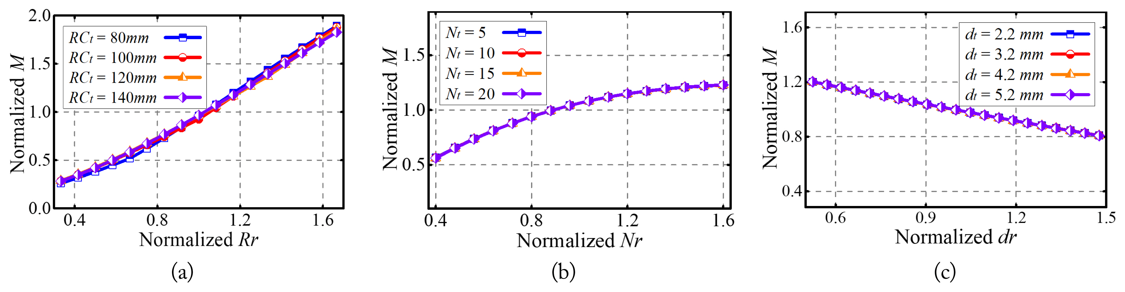
Influence of physical parameters on mutual inductance: (a) outer radius, (b) turns, and (c) pitch.
From Fig. 7, it is evident that changing the transmitting coil does not affect the impact of the receiving coil on mutual inductance. Therefore, when a single-sided coil is optimized, the parameters of the other side can be considered known. Overall, the influence of the physical parameters of a single-sided coil on mutual inductance M can be expressed as
2. Self-Inductive
Mutual inductance is defined as the ratio of the magnetic flux linking one coil to the current-producing magnetic flux in the same coil [31, 32]. Its corresponding equation can be presented as:
where, RCi is the radius of the single-turn coil and ri is the radius of the wire.
All equivalent single-turn coils have the same center—Dt,r =0. The self-inductance of a coil with Nr turns can be formulated as:
According to Eq. (14), self-inductance is mainly influenced by its own turns Nr, radius RCr, pitch distance dr, and wire radius rr. Therefore, during coil design, rr is usually determined based on electrical parameters, such as current and voltage. Only Nr, RCr, and dr are the optimal targets for the coil structure. The results processed using Eq. (11) are presented in Fig. 8, which shows that the changes in the curves are similar to those shown in Fig. 7. The radius RCr and turns Nr are positively correlated with self-inductance Lr, while the pitch dr is negatively correlated with the same. Furthermore, RCr and dr are linearly correlated with Lr. Notably, RCr and Nr correspond to a larger curve slope, meaning that these parameters have a more obvious influence on Lr.
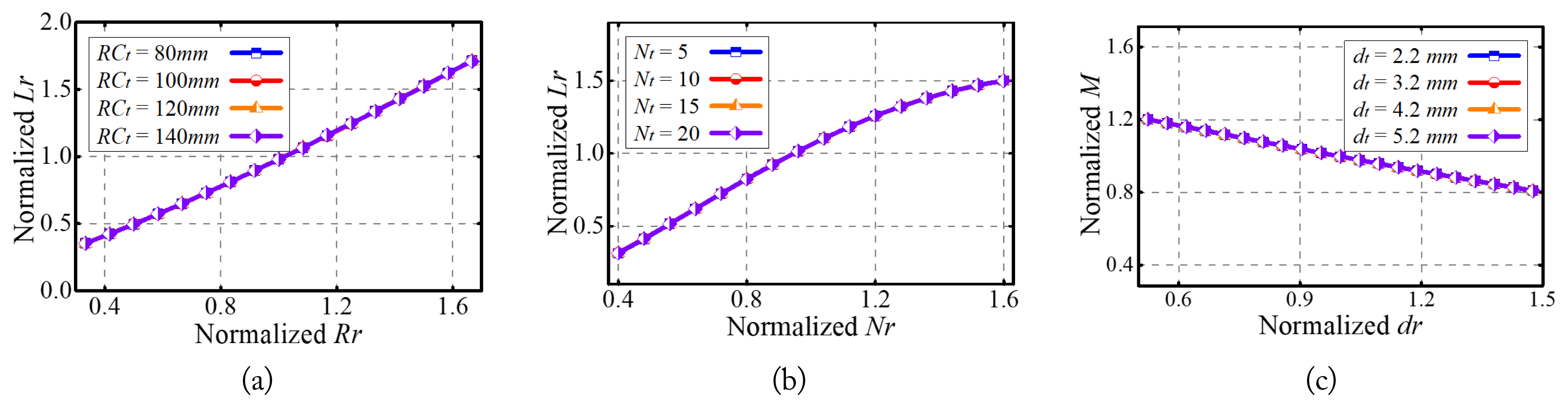
Influence of physical parameters on self-inductance: (a) outer radius, (b) turns, and (c) pitch.
Therefore, the self-inductance of a coil is constrained only by its own physical parameters, which can be expressed as:
3. Resistance
The AC losses of an MCM comprise ohmic losses and radiation losses [7]. Ohmic losses dominate in the low-frequency range, while radiation losses become prevalent at high frequencies. For EV wireless charging, the resonant frequency generally remains between 80 kHz and 100 kHz, thus falling in the low-frequency range. Therefore, in this case, radiation losses can be neglected. As a result, only ohmic resistance was considered in this experiment, which can be expressed as follows:
refers to the pitch, ω denotes angular frequency, and σ indicates conductivity.
According to Eq (16), the AC resistance RAC is influenced by the operating parameters (angular frequency ω), wire material (conductivity σ, wire radius r), and structure parameters (radius RC, turns N, pitch d). Therefore, the proposed design focused on structure parameters. The impact of physical parameters on AC resistance RAC is demonstrated in Fig. 9.

Influence of physical parameters on AC resistance: (a) outer radius, (b) turns, and (c) pitch.
Notably, the curves shown in Fig. 9 were also normalized. The influence of physical parameters on AC resistance RAC is consistent with the overall trend shown in Figs. 7 and 8. The outer radius RCr and turns Nr are linearly positively correlated with RAC, while pitch dr is negatively correlated. Essentially, it is observed that an increase in RCr and N will lengthen the total length of wire l, while the increase in dr will shorten it. Furthermore, Litz wire is usually used in WPT, as it can effectively mitigate the skin effect and proximity effect. There exists a linear relationship between physical parameters and RAC. It is only when dr is very small that it will exhibit a reduced skin effect. In other words, RAC gradually decreases and eventually stabilizes with an increases of dr.
AC resistance RAC is also restricted by radius RCr, turns Nr, and pitch dr, which can be expressed as follows:
Overall, based on the effects of physical parameters on electrical parameters, Figs. 7–9 show that the outer radius RCr, turns Nr, and pitch dr have an almost similar influence on mutual inductance M, self-inductance L, and AC resistance RAC.
IV. Optimization of the MCM
1. Influence of Resonance Frequency
Based on the theories demonstrated above, resonance frequency f is another crucial factor that affects the maximum output power Pout·max. Eq. (6) clearly shows that f influences Pout·max, primary impedance Zt, secondary impedance Zr, and mutual inductance reactance XM. The impact of f and mutual inductance M on transmission performance, based on Eqs. (3)–(5), are shown in Fig. 10, where the black dashed line corresponds to the ideal resonant frequency f0. The area to its right represents the under-compensation area, where the primary reactance Xt and secondary reactance Xr are inductive. Moreover, input power Pin and output power Pout have the same variations. When frequency f reaches close to f0, the maximum output power Pout·max is achieved, while the corresponding mutual inductance M is the smallest. Furthermore, as f increases, the required M for Pout·max increases along with it. This is because when f deviates from f0, Xt/L1=Xr/L2 ≈ 0. This means that the larger the deviation, the larger the Xt and Xr. Since the modulus of the primary and secondary impedances |Zt| and |Zr| are also larger, a larger XM was required. In addition, for the transmission efficiency η in Fig. 10(c), the higher the M, the higher the η. Therefore, η is also affected by f. A small M results in a higher f and lower η. At f0, the required M is at its minimum. This is also why both the primary and secondary sides of an MCM should work in a resonant state as much as possible.

The transmission performance varying with the mutual inductance and frequency: (a) input power (W), (b) output power (W), and (c) transmission efficiency (%).
2. Design of the Receiving Coil
The design process for the receiving coil to obtain the maximum output power Pout·max is shown in Fig. 11. First, the wire radius r, load Rl, and resonance frequency f were determined based on the requirements of EV wireless charging. In a single-sided restricted MCM, the physical parameters of a transmitting coil and its relative spatial position are known conditions. Furthermore, self-inductance Lt and resistance Rl1 of the transmitting coil were determined using Eqs. (15) and (17). For this purpose, the primary and secondary coils with similar or identical structures and parameters were considered the most favorable. Notably, for a restricted receiving coil, the radius RCr should be as close as possible to that of the transmitting coil. Moreover, since the resistance of coils is usually small, Rl1 is generally higher than the resistance of the source and the compensation capacitor. Therefore, it is included in Zt. However, resistance Rl2 of the receiving coil is usually ignored. Additionally, to reduce losses, the influence of the skin effect should be weakened as much as possible. The optimal pitch dr was selected based on f. Subsequently, based on Eq. (6), the optimal impedance XM was calculated. The outer radius RCr, turns Nr, and pitch dr of the receiving coil were selected using Eqs. (12), (15), and (17).
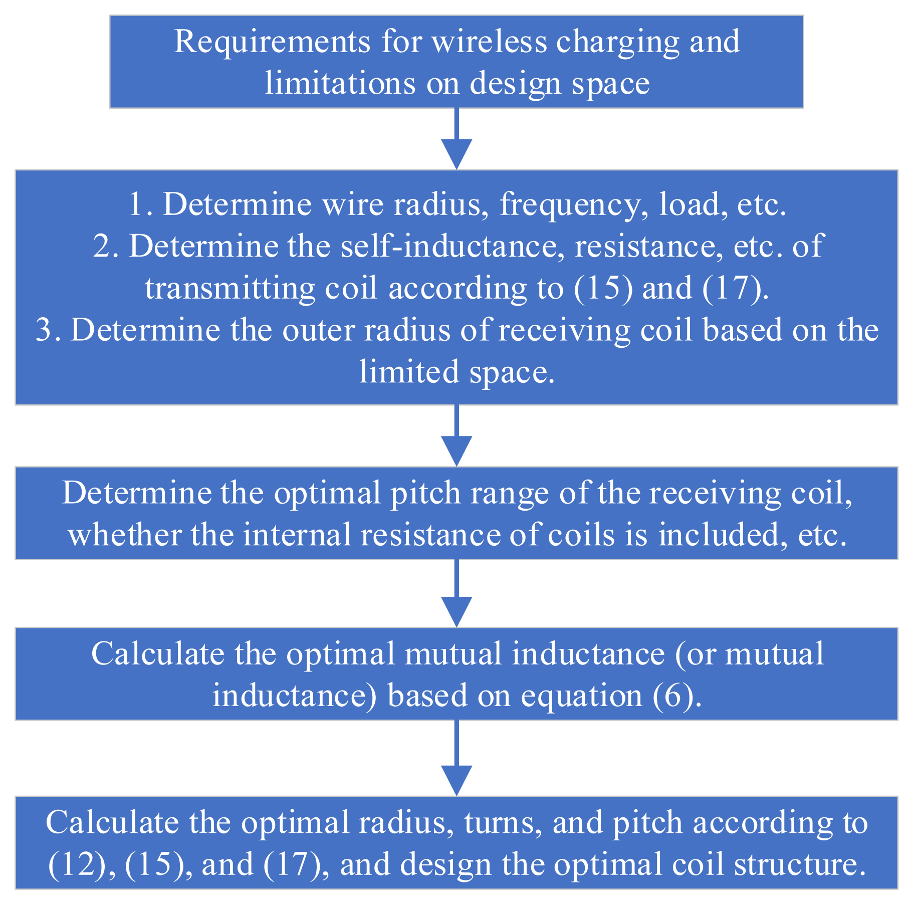
Design flow of an optimal receiving coil.
When both the primary and secondary sides of an MCM are in ideal resonance, Xt =Xr =0, Zt =Rt, and Zr =Rr. The effect of self-inductance Lr of the receiving coil can be ignored, since it only needs to satisfy Eq. (6). In such a case, the turns of the receiving coil can be calculated without accounting for Eq. (15). As shown in Fig. 4, when the resonance frequency f deviates from the ideal value—that is, when it is in non-ideal resonance—an optimal mutual inductance M is present. Therefore, the effects of the self-inductances of both the transmitting and receiving coils must be accounted for in the design process shown in Fig. 11.
V. Experiments
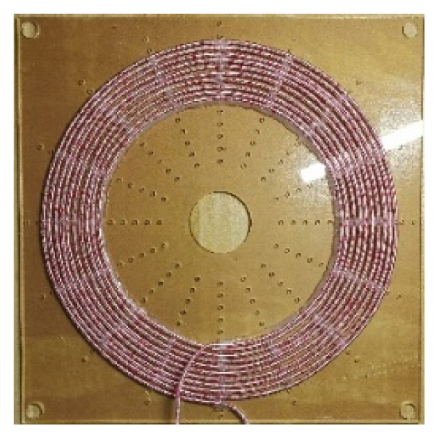
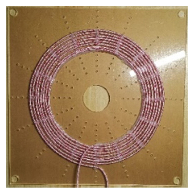
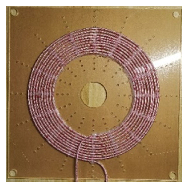
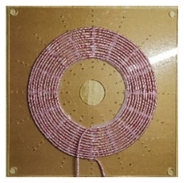
Four coils were wound with 0.1 mm × 500 Litz wire, maintaining a pitch of 5 mm. One of the coils was a transmitting coil, while the other three were receiving coils. The representative symbols and corresponding structures are listed in Table 1, while the physical and electrical parameters of the four coils are shown in Table 2. Excluding the reserved length of the wire, the total lengths of the four coils were 250π cm, 176π cm, 210π cm, and 240π cm. The ratio of wire length to AC resistance was approximately equal, consistent with the theoretical derivation in Eq. (16). Furthermore, the ratio of self-inductance to the number of turns was closely aligned with the law depicted in Fig. 8(b). Notably, the SS compensation topology was selected. Coils and corresponding compensation capacitors together formed the transmitter and the different receivers, ultimately generating different MCMs. The representative symbols and meanings of the transmitter, receivers, and MCMs are presented in Table 3.

Symbols and their means and structures

Physical and electrical parameters of MCM
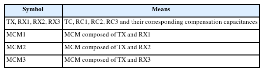
Symbols and their means
The resonant frequency was selected as 85 kHz. A vector analyzer (TH2826) was employed to perform the impedance characteristics. The sweep frequency range was 50 kHz–150 kHz. Notably, compensation capacitances of the transmitter and receivers were adjusted to meet the reactance X of 0 in frequency f = 85 kHz. Fig. 12 traces the variations in X and resistance R with f. It is evident that X increases continuously with an increase in f, changing from negative (capacitive) to positive (inductive). Notably, compensation capacitor banks are composed of standard capacitors (with certain errors). Table 2 presents the actual compensation capacitances calculated. Due to the parasitic capacitances of the coils, the actual compensation capacitances were slightly lower than those calculated based on resonance. Furthermore, the resistances of the transmitter and receivers were approximately the sum of those of the coils and the corresponding capacitors.
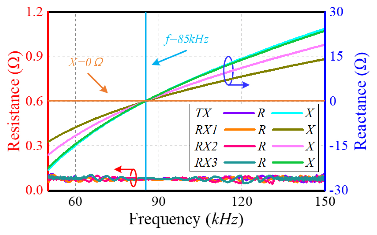
The impedance and resistance varying with frequency.
This study constructed three MCMs, as shown in Table 3. Fig. 13 presents the variation in mutual inductance M with transmission distance D when the transmitting and receiving coils face each other. It is observed that as D increases, M continues to decrease—first fast and then slow. Furthermore, the more turns the receiving coil has, the greater the M of the MCM that it forms. This result is consistent with the theoretical analysis, thus verifying that in a limited space (that is, the radius of coils remains unchanged), the adjustment of turns can ensure that the same M at different D.

Mutual inductance varying with transmission distance.
Under ideal resonant conditions, the load RL remained constant, but the transmission distances D of the MCMs changed (essentially, the change in mutual inductance M in Fig. 13). Furthermore, Fig. 14 shows the variations in output power Pout and transmission efficiency η with the transmission distance D. It is evident that the trends of all three MCMs are the same. As D increases, Pout increases at first and then declines. η shows a continuous downward trend. Furthermore, the more the turns of the receiving coil, the greater the η. All three MCMs achieved maximum Pout at η of around 50%. However, the optimal D corresponding to the maximum Pout was different—25 cm, 27 cm, and 28 cm for the three MCMs.
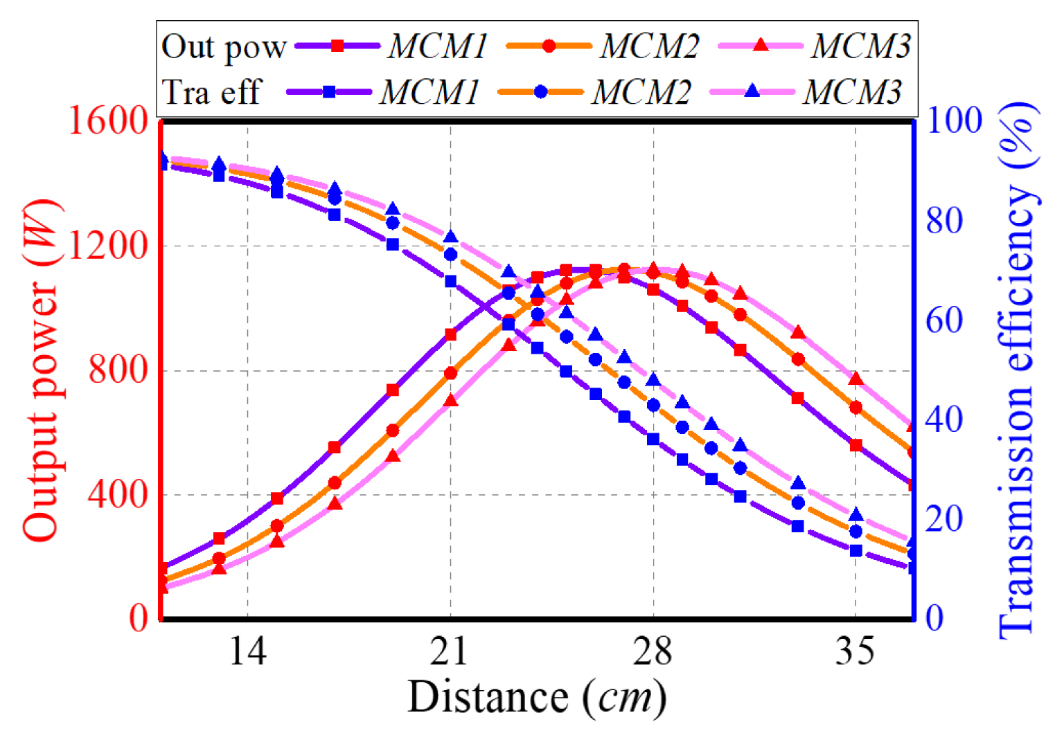
Variations in output power and transmission efficiency with transmission distance.
To achieve maximum output power Pout, Eq. (6) had to be met. At ideal resonance frequency f0, the primary impedance Zt refers to the sum of the resistances of the coil and compensation capacitor, which showed almost no change. Meanwhile, the secondary impedance Zr includes the resistances of the coil, compensation capacitor, and load. Usually, the resistance RL of a load is significantly greater than that of the receiver, with Zr being approximately equal to RL. Notably, the transmission distances D corresponding to the three images are found to be 25 cm, 27 cm, and 28 cm, representing the optimal D corresponding to the different MCMs. The three curves in Fig. 15 correspond to the Pout and η of the three MCMs. Their variations are almost identical to Fig. 14. As RL increases, Pout increases at first and then decreases, while η shows a continuous decreasing trend. Furthermore, the more the turns of the receiving coil, the greater the corresponding optimal RL. Also, the farther the D, the smaller the corresponding optimal RL. Moreover, the three pictures shown in Fig. 15 indicate that the MCMs corresponding to the maximum Pout are MCM1, MCM2, and MCM3. This implies that the change in RL does not affect the optimal D corresponding to the different MCMs.

Output power and transmission efficiency varying with load: (a) transmission distance is 25 cm, (b) transmission distance is 27 cm, and (c) transmission distance is 28 cm.
Under non-ideal resonance conditions, frequency f tends to have an impact on mutual inductance reactance XM, primary impedance Zt and secondary impedance Zr. In theory, as long as Eq. (6) is satisfied, WPT can extract the maximum output power Pout. Fig. 16 presents the variation in output power Pout and transmission efficiency η with f when the mutual inductance M and load RL are constant. Notably, the transmission distances D corresponding to three images remains 25 cm, 27 cm, and 28 cm. However, as f increases, Pout and η first show an increasing trend that ultimately becomes a decreasing trend. The maximum values are achieved around the ideal resonant frequency f=f0. However, the rate of change in Pout is considerably higher than η. Notably, similar to the influence of RL on the maximum Pout, f does not influence the optimal D corresponding to the different MCMs.
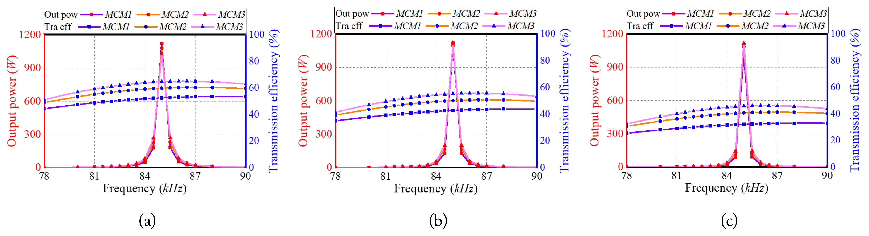
Variations in output power and transmission efficiency with frequency: (a) transmission distance of 25 cm, (b) transmission distance of 27 cm, and (c) transmission distance of 28 cm.
In obtaining the above experimental results using different MCMs, the transmitting coil remained the same. The outer radiuses of the receiving coils were also the same. Furthermore, even when the transmission distance D, load RL, and frequency f changed, there was always an optimal MCM that was able to obtain the maximum output power Pout·max. The only variable for this optimal MCM was the turns Nr of receiving coil. This result verifies the feasibility of taking recourse to the adjustment of turns to achieve maximum output power for MCMs with different primary and secondary coils at a specific position.
VI. Conclusion
This paper presents an optimal design method for achieving the maximum output power from MCMs using different primary and secondary coils. Detailed analyses were conducted on the impact and variation of the physical parameters on the electrical characteristics. Considering a confined space, the maximum power output for a specific transmission distance was achieved by optimizing the structural parameters of the coil. A design process for this optimal coil was also summarized. Three different MCMs were built, and relevant experiments were conducted on a 1 kW experiment platform. The differences between the best mutual inductances corresponding to the maximum output power were verified at different transmission distances, loads, and resonance frequencies. Notably, the results were found to be consistent with those of the simulations and theories, thus verifying the feasibility of the proposed optimal method.
Acknowledgments
This work was supported in part by the National Natural Science Foundation of China (Grant No. 52307008, 52122701, 51977147, and 52077153), in part by the Natural Science Foundation of Tianjin City (Grant No. 22JCZDJC00620), in part by the State Key Laboratory of Reliability and Intelligence of Electrical Equipment (Grant No. EERI_OY2022006), and in part by the S & T Program of Hebei (Grant No. 21567605H, 215676146H, and 225676163GH).
References
Biography

Zhongyu Dai, https://orcid.org/0000-0002-4574-405X received his B.S. and Ph.D. degrees in electrical engineering from the School of Electrical Engineering and Automation, Wuhan University, Wuhan, P. R. China, in 2014 and 2020, respectively. After this, he joined the School of Power and Mechanical Engineering as a postdoctoral researcher. He is currently an associate professor in the School of Electrical Engineering at Hebei University of Technology. His main research interests include wireless power transmission technology and its applications, and condition monitoring of smart grids.

Wenxi Peng received his B.S. degree in electrical engineering from Wuhan University, Wuhan, P. R. China, in 2014. He then joined the State Grid Sichuan Ultra High Voltage Company, where he worked in the field of relay protection. He is currently the leader of the substation maintenance team at State Grid Sichuan Ultra High Voltage Company, as well as a skilled craftsman and young talent recommended by the State Grid Sichuan Electric Power Company. His main research interests include relay protection, professional management, and plan management.

Yake Tang received his B.S. and M.S. degrees in electrical engineering from the School of Electrical Engineering and Automation, Wuhan University, Wuhan, P. R. China, in 2015 and 2017, respectively. He is currently an intermediate engineer at the Henan Electric Power Company Economy Research Institute. His main research interests include the design and research of transmission lines.

Haoran Xu is currently working toward his M.E. degree in electrical engineering and automation from Donghua University. His main research interests include the engineering electromagnetic field and power electronics technology.

Huihui Wang received her B.S. degree in electrical engineering from Shandong Agricultural Engineering University. She is currently working toward her M.E. degree in electrical engineering from Hebei University of Technology, Tianjin, China. Her research interests include wireless power transfer and its industrial applications.
Yanhu Zhai received his B.S. degree in electrical engineering from Shijiazhuang Tiedao University. He is currently working toward his M.E. degree in electrical engineering at Hebei University of Technology, Tianjin, China. His main research interests are wireless power transmission technology and its applications.

Ming Xue, https://orcid.org/0000-0001-6153-9761 received his B.S. and M.S. degrees from Tianjin Polytechnic University, Tianjin, China, in 2011 and 2014. In 2022, he received his Ph.D. degree in electrical engineering from the Hebei University of Technology, Tianjin, China. He is currently an associate professor with the School of Electrical Engineering, Hebei University of Technology, Tianjin. His current research interest include wireless power transfer technology and its application.

Xian Zhang, https://orcid.org/0000-0002-0925-9831 received his M.E. and Ph.D. degrees in electrical engineering from Hebei University of Technology, Tianjin, China, in 2009 and 2012, respectively. He is currently a professor at Hebei University of Technology, Tianjin, China. He is the director of the China Electrotechnical Society and the secretary-general of the National Specialized Committee on Wireless Power Transmission Technology. His research interests encompass intelligent high-power wireless power transmission technology, measurement of three-dimensional electromagnetic fields, and numerical calculations of modern engineering electromagnetic fields.