I. Introduction
Unlike an imaging system that captures images using optics, the synthetic aperture radar (SAR) system acquires images by directing radio waves at a target and then measuring the reflected signal. This means that it is free from the influence of environmental conditions, such as bad weather, clouds, and dust, and observations are possible regardless of the time of the day [1].
Among the many ways available for operating SARs, most studies have been conducted on the monostatic mode, which operates using only one satellite platform because of its easy control and low complexity of geometry analysis [2]. However, since the monostatic mode operates by using only one satellite platform, limitations related to SAR system performance and related geometric problems often arise as a result of inflexible platform operation [3].
In this context, bistatic SAR systems have gained significant military and civilian attention in recent years. It has enhanced the capability of remote sensing missions in the areas of anti-jamming, covert instrument detection, and configuration flexibility [4, 5]. In addition, it exhibits better performance than monostatic SAR systems for several pertinent variables, such as signal-to-noise ratio (SNR) and spatial resolution, by appropriately utilizing the bistatic platform structure [6]. Because of these advantages, several SAR missions, such as TanDEM-X by the German Aerospace Centre—a high-resolution X-band SAR using phase array technology—and RADARSAT-2/3 developed by the Canada Center for Remote Sensing, have been conducted to investigate the bistatic SAR mode [7, 8].
One of the major interests of these SAR missions has been analyzing performances, such as those of resolution, noise-equivalent sigma zero (NESZ), and range/azimuth ambiguity. Since the performance of a SAR system greatly influences the quality of the images obtained from SAR sensors, studies analyzing SAR performance have been actively conducted. With regard to the monostatic mode, considerable effort has been directed at improving image quality by analyzing the ambiguities of the SAR system [9, 10]. Furthermore, an appropriate quad-pol SAR was designed by drawing on a performance analysis of antenna characteristics [11].
In the performance analysis of bistatic SAR systems, the separation of the transmitter and receiver means that additional considerations must be made based on the geometric configurations of the system. In the literature, the performance analysis of bistatic SAR has included investigations into SNR, resolution, and NESZ in spaceborne–airborne and inter-spaceborne operating environments [6, 12]. Spaceborne bistatic SAR is primarily operated in a repeat-pass scenario along one path, which offers an advantage in interferometry processing, since two satellites repeatedly investigate the same path [12]. However, various configurations of the bistatic SAR system must be explored to improve performance by adjusting the positional relationship and direction of progress to ultimately meet the goal of each SAR mission.
The performance of bistatic SAR systems is highly affected by their geometry and the scenario of operation. In spaceborne SAR environments, parallel trajectory configurations [13], in which two satellites are operated parallelly at the same altitude and speed, offer the advantages of reduced geometric and radial distortion as well as pointing and timing synchronization [2]. Notably, the optimum geometric configuration of a parallel trajectory can be designed by conducting a performance analysis of bistatic SAR systems. In a parallel trajectory bistatic SAR system, the baseline—the distance between two satellites—must be carefully determined from a timing diagram. In particular, both the arrival time of signals received through a direct path and the path reflected onto the Earth’s surface must be accounted for in the timing diagram to attain the optimum design.
In this paper, the baseline of the bistatic spaceborne SAR system is first determined to identify the largest observation area from a timing diagram of the two satellites flying parallelly at the same altitude and speed. The resolution, NESZ, range ambiguity-to-signal ratio (RASR), and azimuth ambiguity-to-signal ratio (AASR) performances of the SAR system are investigated using the determined geometric configurations. After selecting the optimum observation area from the calculation results, a comparison of the results for the forward and backward operations of the transmission/reception satellites operating in the monostatic mode is conducted to determine the operation scenario offering better results.
II. Baseline Determination in Bistatic SAR
Fig. 1 shows the configuration of a spaceborne, parallel trajectory, bistatic SAR system where the transmitting and receiving satellites move in a parallel flight path at the same altitude and speed. In bistatic operations, the transmitter is assumed to be at Trajectory 1 and the receiver at Trajectory 2. For comparison, a monostatic SAR mode was also assumed to operate at Trajectory 1 or 2. In Fig. 1, the distance between the two satellites or the baseline is denoted by B, the altitude of the satellites is H, and the look angle at the transmitter is represented as θL. Notably, the transmission/reception satellites were synchronized and operated in simultaneous transmission mode. Notably, for a given pulse repetition frequency (PRF), the bistatic SAR in Fig. 1 bears the blind look angle at which the return signals travel along path rT+rR to reach the satellite during transmission.
In spaceborne bistatic SAR systems, two additional signals reach the receiver [14]. One is the direct signal from the transmitter to the receiver through baseline B. The other is the common plane specular echo reflected by the Earth’s surface between the two satellite trajectories along path length 2rs.
In Fig. 2, the timing diagram of a spaceborne bistatic SAR is displayed for H = 500 km and B = 200 km. The red stripes represent the blind look angle, while the blue and green stripes are the footprints of the direct signal and the common plane specular echo, respectively. The direct signal and the specular echo disturb the sensing of return signals from the observation area. Therefore, for a fixed PRF, swath widths are limited only to the look angles that do not correspond to the blind angles and are not disturbed by the direct signal and specular echo. As shown in Fig. 2, for a PRF of 14,400 Hz, the observable area for the bistatic SAR is quite narrow for B = 200 km. Furthermore, the frequency of the PRF range is slightly higher than expected. This may be attributed to the antenna used in the simulation in this study, which was manufactured by the authors in their own laboratory, with dimensions of 1.5 m width and length in a parabola configuration [15]. Notably, the PRF should be high enough to be high enough to avoid ambiguity.
To obtain the widest swath width, the stripes of the direct signal and specular echo must overlap with those of the blind angle. Although Fig. 2 indicates that an overlap of three stripes is not realizable for all PRFs, this can be achieved by adjusting the baseline of a specific PRF. To identify the proper baseline and PRF for a given H, this study took recourse to forbidden arrival times, expressed as Eqs. (1)–(3), where T is the pulse repetition interval (PRI) of the transmitted signal and l, m, and n are the integers including zero.
In particular, tD(l) and tE(m) are the forbidden arrival times resulting from the direct signal and the specular echo, respectively, while tB(n) is the forbidden time for transmission. If three forbidden arrival times occur at the same time, the forbidden look angle can be minimized.
For a specific PRF, the baselines satisfying tD =tE can be easily estimated. However, the tB might not always coincide with the other two since it is quantized by the PRI. For instance, in Fig. 2, it can be observed that for B = 200 km, the tD coincides with tE at PRF = 14,300 Hz, but tB has different values. Fig. 3(a) displays the arrival times when the baseline changes for PRF = 14,300 Hz. The tD(blue) and tE(green) are coincident for B = 175 km and 200 km, but the tB does not coincide for both baselines. Therefore, to find the accurate PRF and baseline at which three arrival times coincide simultaneously, repeated calculations are necessary. As the PRF changed, the baselines satisfying tD =tE were first identified, and then their coincidence with tB was checked. After conducting iterations of the above process, the proper PRF and baseline at which the three signals arrived simultaneously were identified. For PRF = 14,400 Hz, Fig. 3(b) shows that tD =tE for B = 182 km and 208 km, but the arrival times of the three signals collapse into the same instance only for B = 208 km.
The timing diagram for the baseline of 208 km is presented in Fig. 4. It is observed that when the PRF is 14,400 Hz, the stripes for the direct and specular echo merge into those of the blind look angle at incidence angles of 27.9°, 31°, and 34°. Subsequently, three observation areas with maximum swath width were achieved for three incidence angle ranges—from 28.8° to 30.2°, from 31.8° to 32.9°, and from 34.2° to 35.2°.
III. Bistatic SAR System Performance Evaluation
In Section II, SAR system parameters were selected using the timing diagram, with the baseline being 208 km, the PRF being 14,400 Hz, and the three incidence angle ranges being 29° to 29.8°, 31.8° to 32.9°, and 34.2° to 35.2°. The performance of the bistatic SAR system was analyzed in terms of relevant performance variables, such as ambiguity ratio, NESZ, and resolution, as was the case with the monostatic mode.
However, unlike the monostatic mode, the bistatic mode operates using two satellites—one set to be only a receiver and the other set to operate in the monostatic mode (operates both Tx and Rx). As a result, the system parameters, such as incidence angle and slant range, changed depending on the location of the monostatic satellite. Since such changes affect the performance of the SAR system, a performance analysis was conducted by classifying the monostatic satellites into cases in which a satellite is set to be in the monostatic mode. As shown in Fig. 1, this study divided the signal trajectory into two parts—the left monostatic placement and the right monostatic placement. Notably, since the position of the satellite remained unchanged, it did not affect the timing variables. For both cases, the performance of the bistatic SAR system was analyzed, and each performance was compared based on the monostatic operating position.
1. Ambiguity-to-Signal Ratio
The ambiguity-to-signal ratio comprises the RASR and the AASR, representing the ratio of undesired signals to the desired SAR signal. The RASR can be calculated using the transmission/reception gain Gt(θ)/Gr(θ); , the transmission/reception slant range rT/rR, the bistatic angle β, the aspect angle ψ, and the angle at which the ambiguity signal occurs in the range direction angle θA. In particular, bistatic RASR can be expressed as in [13, 16]. Notably, when receiving the n-th signal, the ambiguity ratio can be calculated using the ratio of the n-th received signal to the other signals.
(4)
Unlike the monostatic mode, the bistatic RASR reflected parameters such as the transmit/receive gain (Gt/Gr), the bistatic angle (β), the aspect angle (ψ), and the transmit/receive slant range (rT/rR) caused by the separation of the transceiver. When the PRF reached 14,400 Hz, the baseline with the maximum swath width was assumed to be 208 km. It was also assumed that the two satellites maintained the same speed at an altitude of 500 km, as well as the same baseline and fly parallel, and that both were operating in stripmap mode.
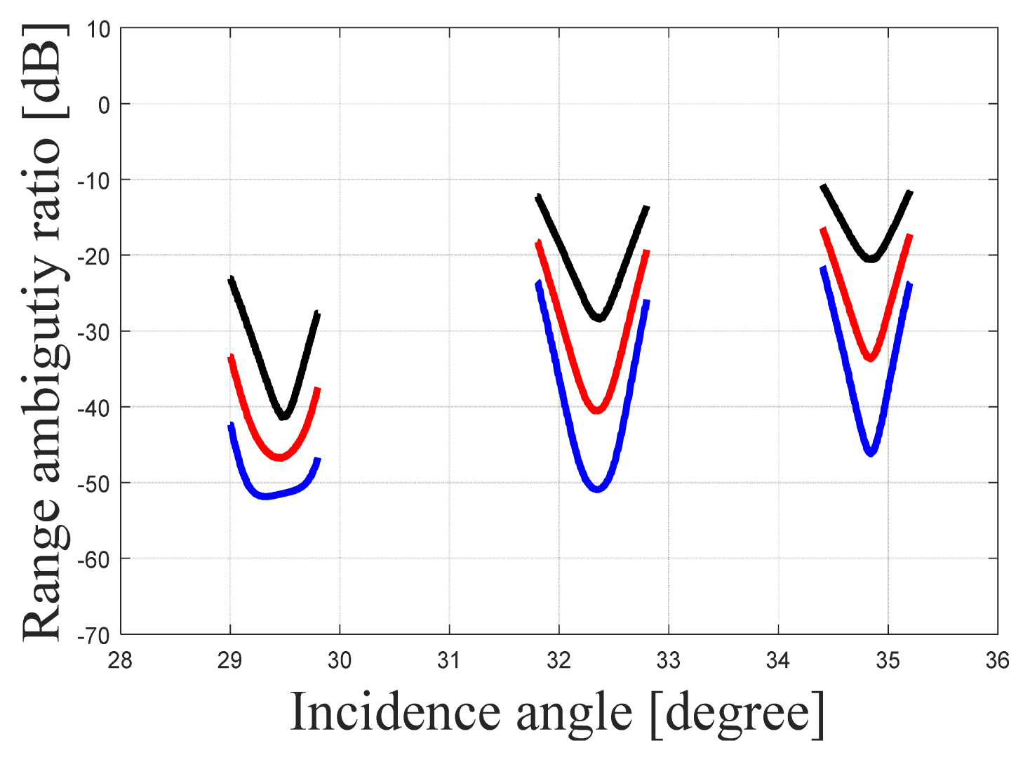
Fig. 5 shows the bistatic RASR performance results with regard to the baseline. As the right-side satellite (receiver only) approaches the left-side satellite (monostatic mode), the performance tends toward being similar to the monostatic mode, and it ultimately matches the monostatic RASR when the baseline reaches 0 km. Fig. 6 shows the results of the RASR for the three observation areas obtained from the bistatic timing diagram. In the bistatic mode, the incidence angles 28.8° to 30.2°, 31.8° to 32.9°, and 34.2° to 35.2° achieve a minimum RASR of −47 dB, −41 dB, and −33 dB, respectively. Furthermore, as the incidence angle increases, the slant range with the target becomes longer, leading to the increased reception of undesired signals and ultimately resulting in increased range direction ambiguity signals. Notably, in the monostatic mode, the left arrangement for the three observation areas attained a minimum RASR of −41.3 dB, −28.4 dB, and −20.5 dB. Notably, the right arrangement received fewer ambiguity signals because it was located close to the target, so it exhibited the best range ambiguity performance.
Unlike the monostatic mode, the AASR in the bistatic mode reflected the gains attained on transmission and reception, which can be expressed as follows:
where θAZ is the azimuth angle.
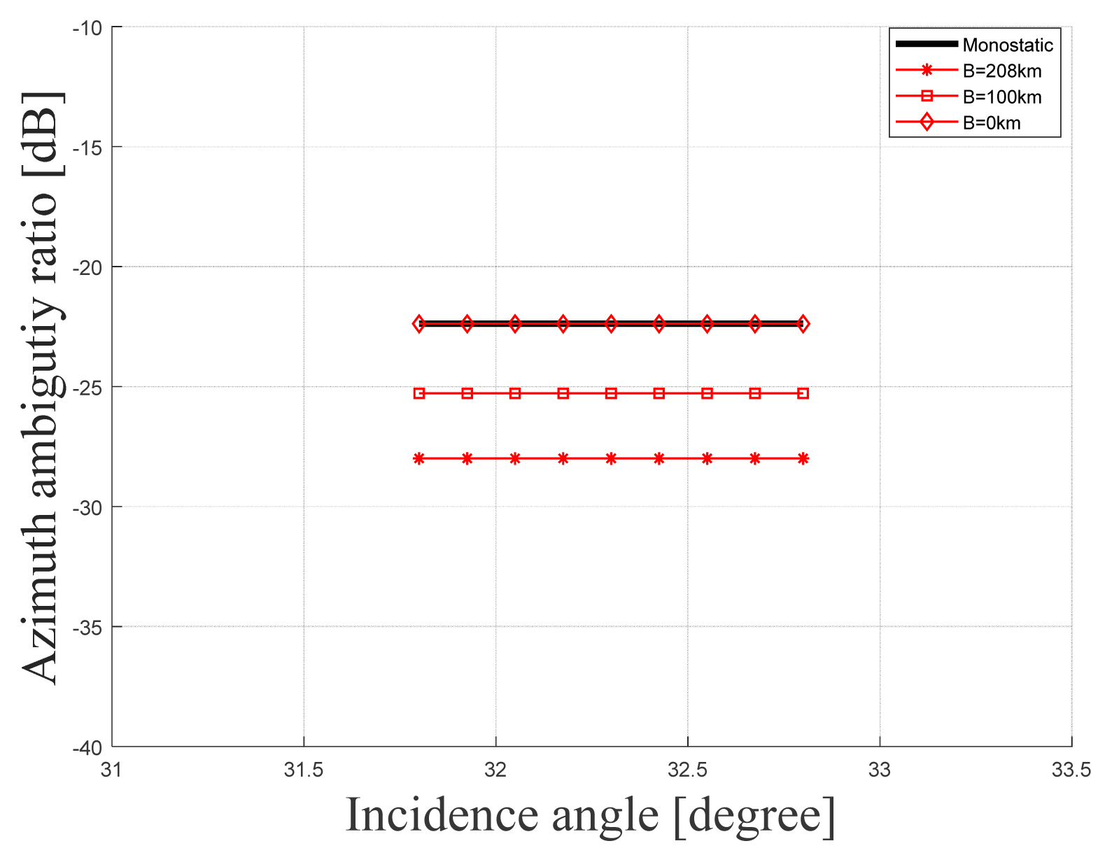
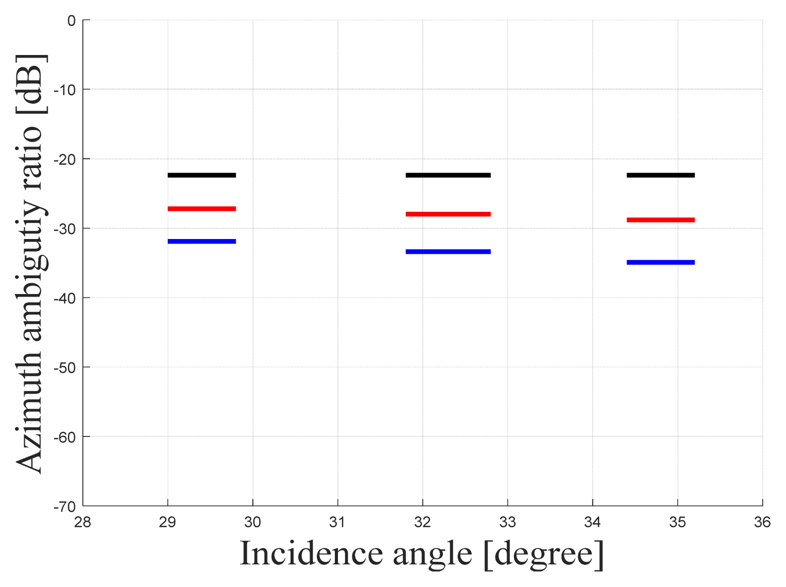
Fig. 7 depicts the bistatic AASR based on the baseline. Similar to the RASR simulation, as the right side of the satellite gets closer to the left satellite, the AASR tends to respond in the same way as the monostatic AASR did, ultimately matching the monostatic AASR when the baseline reaches 0 km. Fig. 8 shows the results of the AASR for the three observation regions obtained from the bistatic timing diagram. In the bistatic mode, the AASR was found to be −28 dB, with the left and right monostatic placements being −22 dB and −31 dB, respectively. Notably, since AASR is affected by changes in the azimuth pattern near the angle at which the azimuth signal occurs, no significant change was observed for any of the cases, even when the incidence angle changed. Furthermore, since the distance from the target was lesser for the right arrangement than for the left arrangement in the monostatic mode, the former attained a large azimuth angle. For this reason, the AASR of the right arrangement achieved a lower value, as it received the signal from the small sidelobe of the antenna pattern.
2. Resolution
Similar to the monostatic mode, the bistatic SAR system resolution depends on the bandwidth of the antenna. However, in contrast to the monostatic mode, the bistatic mode considers the bistatic angle and aspect angle reflecting the positional relationship between two satellites instead of the incidence angle in the range direction, as considered by the monostatic mode.
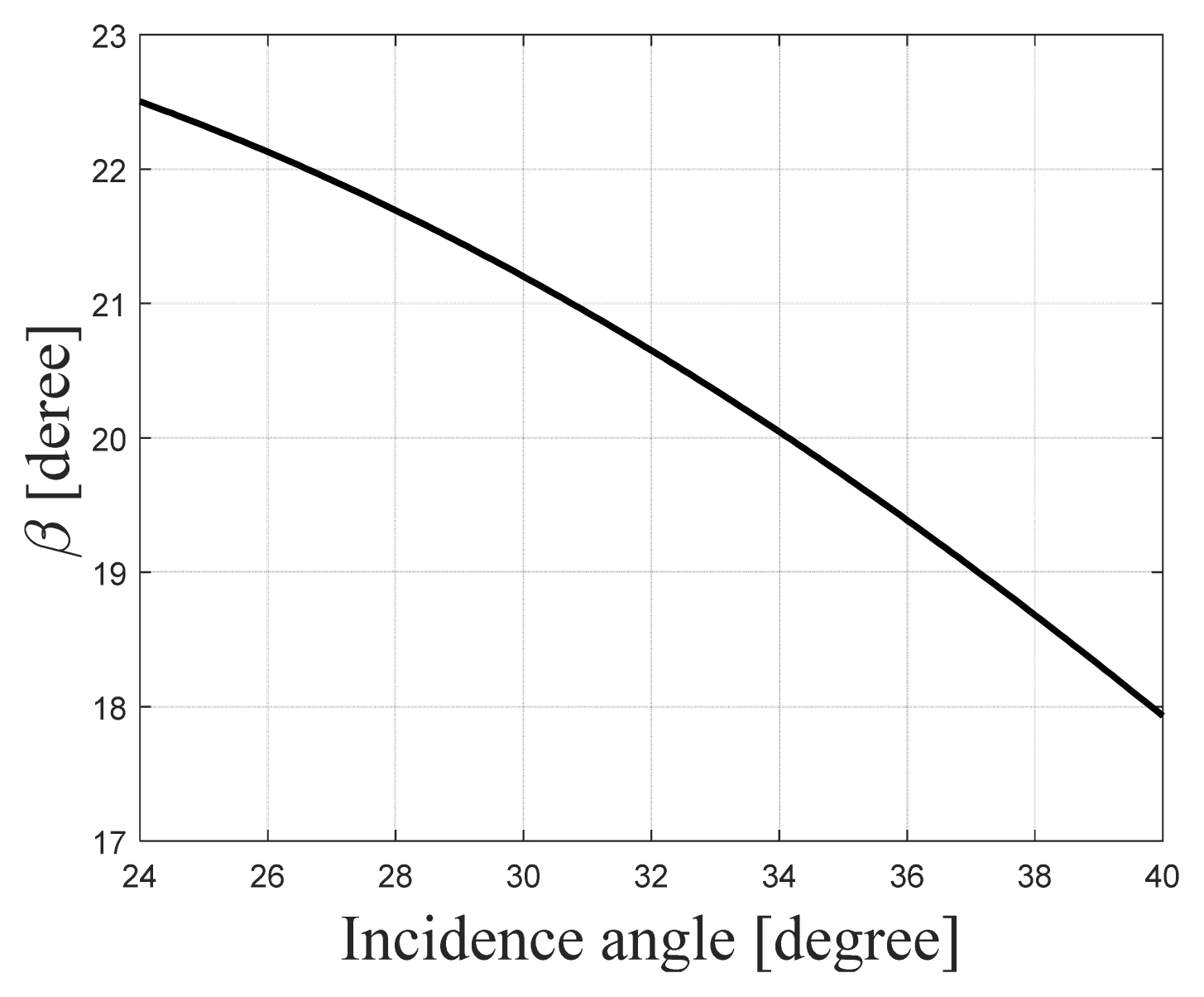
Variations in the bistatic angle were directly affected by the baseline. Notably, the bistatic angle is often used as the angle that replaces the incidence angle in the bistatic SAR, as shown in Eq. (7). Fig. 9 presents the bistatic angle in terms of the angle of incidence when the baseline is fixed at 208 km.
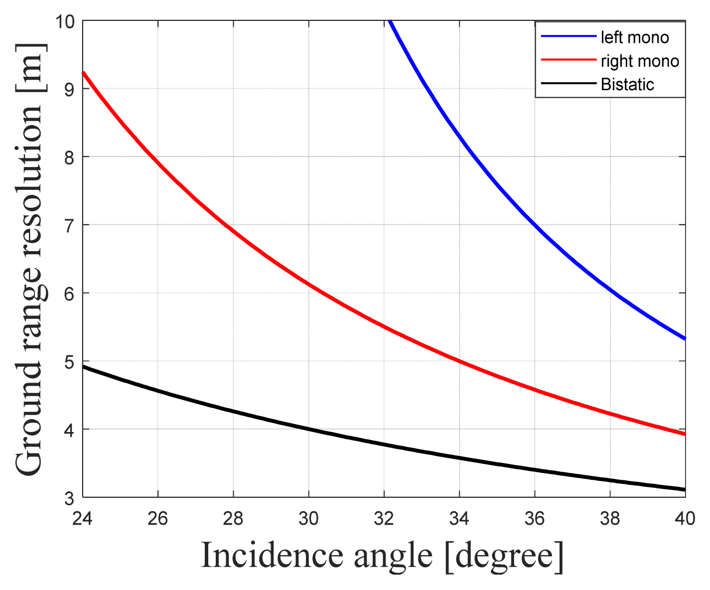
As shown in Fig. 10, the bistatic mode has a resolution of 6 m or less when the incidence angle is 30.4° or more. This indicates that the required performance is satisfied only for the observation areas in Cases 2 and 3 of Fig. 4. Furthermore, in the case of the monostatic mode, the ground range resolution was quite large in the forward arrangement (right placement), since the incidence angle decreased significantly compared to the backward arrangement (left placement), while the resolution value increased significantly in the process of reflecting the ground range of the SAR. In addition, as the incidence angle increased, the sin(θi) and cos(β/2)cos ( ψ) terms also increased, as a result of which improvements in the ground range resolution performances of both monostatic and bistatic SAR were observed.
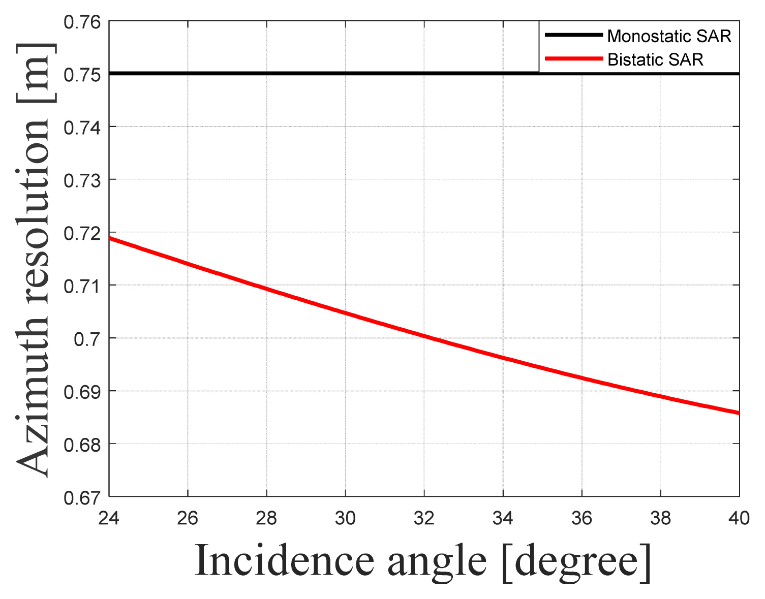
The bistatic azimuth resolution expressed in Eq. (8) reflects the ratio of the slant range of the transmitter to the slant range of the receiver [3], with LT being the size of the transmission satellite antenna.
The results obtained by comparing the azimuth resolution performances of the monostatic SAR and bistatic SAR using Eq. (5) are shown in Fig. 11. It is observed that the bistatic SAR satisfies the required performance for all incidence angles and maintains the same azimuth resolution regardless of the location of the monostatic SAR. Furthermore, rT is larger than rR, which means that the bistatic azimuth resolution performs better than its counterpart. It is further observed that as the incidence angle increases, rT becomes longer and the azimuth resolution value becomes lower.
The NESZ, an indicator of sensitivity performance, investigates the new variables arising from a bistatic SAR system operating two satellites—the distance between the two satellites and the gain of each transmitting/receiving antenna. Here, Pt is the transmission power, GT is the transmission antenna gain, GR is the reception antenna gain, λ is the wavelength, k the Boltzmann constant, Vs is the satellite speed, τ is the pulse width, T0 is the thermal noise, NF is the constant noise, BW is the transmission bandwidth, and Lt is the system’s total loss.
The slant range of the two satellites was obtained from
r T r R r R 2 + r T 2 cos ( β 2 ) cos ( ψ )
All three bistatic modes achieved a value of −20 dB or less. Moreover, in the case of the monostatic satellite, the slant range of the transmitter was large—about 1 dB larger than that of the bistatic mode. In contrast, since the slant range was short in the bistatic mode, its sensitivity performance was better.
IV. Conclusion
This paper analyzed the performance of a bistatic SAR system for two parallelly flying satellites, as well as the performance achieved utilizing a monostatic mode satellite operating in backward and forward directions. In the case of the bistatic mode, when the PRF was 14,400 Hz, a baseline of 208 km was set to guarantee the maximum swath width of the SAR system.
Furthermore, the observation area was divided into three separate cases for performance analysis. The results showed a ground range resolution of less than 6 m for Cases 2 and 3 of Fig. 4, while the azimuth resolution of all cases met the targeted performance. In addition, while the NESZ and RASR of all cases satisfied the expected performance, the AASR produced satisfactory results only for Cases 1 and 2.
Since Case 2 satisfied the targeted value for all performance indicators, its values were determined as bistatic SAR system parameters. Therefore, for the monostatic operation, a performance analysis was performed only on the observation area pertaining to Case 2, as it was determined as the bistatic SAR system. Furthermore, in the case of ground range resolution, the performance of the backward arrangement was 5.8 m—significantly better than the 10.1 m of the forward arrangement. The azimuth resolution exhibited similar performance. In the case of NESZ, the forward arrangement was observed to be better, at −28.2 dB, due to its close slant range and small incidence angle. Although the RASR differed significantly from the targeted performance at −10.2 dB in the backward placement, its performance remained below −22 dB in the case of the forward placement, thus satisfying the target performance. Furthermore, AASR satisfied the expected performance in both cases. Overall, when using an SAR system that meets the target performance of 10 m or less for range resolution, a forward arrangement that exhibits overall good performance with regard to the indicators should be selected, while a backward arrangement should be preferred in cases where more precise performance is allowed for range direction ambiguity. These results confirm that when setting up a bistatic SAR system, the ground range resolution deteriorates with a decrease in the receiver’s distance from the target, but the ASR tends to improve. Furthermore, optimized variables can be set based on a comparison of the bistatic and monostatic performances in this paper.