A Novel Compact Ultra-Wideband Frequency-Selective Surface-Based Antenna for Gain Enhancement Applications
Article information
Abstract
This article presents a compact ultra-wideband (UWB) circular monopole antenna with a frequency-selective surface (FSS) for gain enhancement. The proposed antenna has a circular patch with circular cuts at the edges and is excited by a microstrip feed. The bottom plane is truncated and further modified by two triangular cuts at the sides and one rectangular cut in the middle to improve the radiation characteristics of the UWB antenna. The antenna is designed on an FR-4 substrate with a thickness of 1.6 mm, a relative permittivity of 4.3, and planner dimensions of 30 mm × 30 mm. To improve the proposed antenna’s gain, an FSS is designed that consists of periodic unit cells of metal printed on the upper layer of an FR-4 substrate with dimensions of 0.11λ × 0.11λ at the lowest operating frequency of 3.3 GHz. The FSS shows a very low transmission coefficient and linearly reducing reflection phase with increasing frequency over a frequency range of 3.3–10.8 GHz. The gain of the proposed antenna is increased from 3 dB to 8.1 dB at 9 GHz by placing the antenna on the FSS. Moreover, the prototype of the proposed antenna is fabricated, and the experimental results are measured, which show close agreements with simulated results. The FSS-based antenna has directional radiation patterns, making it a potential candidate for ground-penetrating radar and UWB applications.
I. Introduction
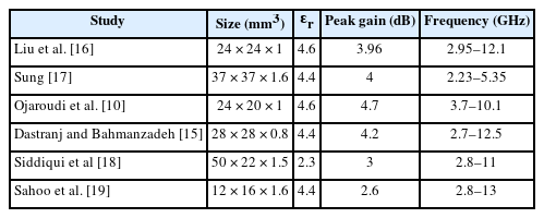
In recent years, ultra-wideband (UWB) technology has appeared as an auspicious candidate for both military and commercial wireless communication applications [1–3]. The allocated spectrum for UWB communication by the Federal Communication Commission (FCC) ranges from 3.1–10.6 GHz. Due to promising radiation characteristics, such as large bandwidth, higher data rate, and minimal power requirement, UWB antennas have been widely used in precision locating, tracking applications, radar imaging, and various other commercial applications [4–8]. This significance inspired the researchers to further investigate UWB antennas. To obtain UWB performance, various design techniques, such as slotted patch antennas with a partial and slotted ground plane, stubs in the ground, and monopole antennas with rectangular, U-shaped, circular, elliptical, and even more complex structures, have been frequently reported in the literature [9–15]. In [9], elliptical and circular-shaped UWB antennas are presented, which are formed by the intersection of two circular or elliptical shapes, covering the UWB spectrum from 3.1–10.6 GHz. In [10], a rectangular-shaped UWB antenna is reported. The rectangular patch consists of two rectangular slits with a modified bottom surface of an inverted T-shaped notch, which improves the bandwidth that ranges from 3.12–12.73 GHz. In [11], a printed wideband elliptical antenna is reported for UWB applications. The top layer consists of an elliptical radiating patch, which is excited by a coplanar waveguide (CPW) feed, and the bottom surface consists of a trapezoid shape. The radiating patch achieved a wideband from 1.02 GHz to 24 GHz. In [12], a new method is introduced to reduce the effects of the ground plane on the elliptical UWB antenna’s performance. To minimize the effects, a rectangular slot is made in the ground plane to improve the radiation characteristics of the reported antenna. In [13], a novel CPW-fed radiating patch with a half-elliptical structure with two symmetrical stubs on the ground surface is presented. The antenna achieved an impedance bandwidth of 6.4 GHz, with an average gain of 4.5 dB. In [14], a compact UWB monopole antenna for automotive applications is reported. The reported structure has a complex geometry and is designed with half-square and half-circular ring shapes. The bottom plane is defected to enhance the impedance bandwidth of the proposed antenna. In [15], a simple planar UWB antenna is presented. To attain UWB characteristics with a compact size, the ground plane is modified with L-shaped inverted open-ended slits. Moreover, the bandwidth is further improved by cutting the radiating element. Furthermore, to enhance the impedance bandwidth of the radiating patch at center frequencies, another inverted L-shaped cut is made on the bottom surface. Various antennas are reported for UWB applications i.e. open slot antenna, wide slot antenna, novel printed UWB antenna and planar UWB antenna. Wide slot antenna has narrow bandwidth while other antennas have low gain [10, 15–19] (Table 1).
Comparision of the proposed antenna with some other similar work
In addition to UWB characteristics, small-sized antennas are essential for compact wireless devices. Thus, several works have been reported recently with compact and low-profile antenna designs with UWB properties [20–22]. However, their low profile makes it difficult for these antennas to attain a high gain over the entire bandwidth. Consequently, UWB antennas have poor directivity. On the other hand, some particular wireless communication applications, such as location tracking, radar, and positioning systems, necessitate highly directive antennas with a high gain [23]. To enhance the gain, various techniques have been investigated and reported in the literature, including defected ground structures (DGS), dielectric resonator antennas (DRAs), array antennas, electromagnetic band gap structures (EBGs), and parasitic elements [24–27]. In addition to the above-mentioned techniques, frequency-selective surfaces (FSS) have recently drawn the attention of researchers for gain improvement. Several literary works have employed FSS for gain improvement [28–32]. The work in [28] proposed an UWB antenna with substrate dimensions of 30 mm × 60 mm. For gain enhancement, a two-layered FSS reflector was employed, and hence, a 3–4 dB improvement in gain was obtained. Similarly, the UWB antenna reported in [29] used a double split ring metasurface as a reflector to improve gain. An overall gain improvement of 5.5 dB was attained for this design. Another leaf-shaped UWB antenna was presented in [30], with overall dimensions of 40 mm × 30 mm. This structure involves dual FSS layers to increase gain. As a result, an enhancement of 2–4.5 dB in gain was achieved with an overall peak gain of 8.7 dB. Likewise, another work [31] proposed two FSS reflector designs (FSS1 and FSS2), with overall dimensions of 82.5 mm × 82.5 mm and 62.5 mm × 62.5 mm, respectively, to improve the UWB antenna gain. An improvement of 2.5 and 2 dB in antenna gain was obtained for the proposed structures, respectively. The UWB antenna reported in [32], with geometrical dimensions of 41 mm × 34 mm, employed a single-layered FSS for gain enhancement. This structure achieved an improvement of 2–3.5 dB in antenna gain with a maximum gain of 7.6 dB over the entire resonant band. Most of the previously reported works, as discussed above, are UWB antennas with double layered FSS structures, which increase not only the overall antenna size but also the fabrication complexity. These multilayered designs have limited practical applications due to their bulky structures. Moreover, the gain enhancement is low for some of the designs.
To deal with the above-mentioned challenges associated with UWB antennas and overcome the limitations of the earlier-reported works, this article presents a high-gain antenna for UWB communication. The proposed design is a circular-shaped antenna with three semicircular patches cut out at the edges of the radiator. The rectangular and triangular slots on the ground plane achieve good impedance match in the UWB range. For gain enhancement, a single-layered FSS reflector is employed. Simulated and measured results ascertain that the proposed antenna with FSS attains a gain improvement of nearly 3 dB. Thus, the compactness, simple structure, high gain, and UWB characteristics validate the suitability of the proposed antenna for modern communication systems.
II. Antenna Design and Characterization
1. Antenna Geometry
The proposed antenna consists of a circular radiating patch on the upper side of a substrate of size Ls × Ws × hs, as shown in Fig. 1. The circular patch has semi-circular cuts at the edges to improve the radiation characteristics of the radiating element. The antenna is fed by a simple micro-strip feed with the length of feed (lf) and width of feed (wf). The antenna is designed on a low-cost FR4 substrate with a relative permittivity (ɛr) of 4.3 and tangent loss (tanδ) of 0.02. The bottom layer of the substrate consists of a partial ground further optimized by etching a rectangular and two triangular-shaped slits to attain the UWB characteristics. The design Eqs. (1), (2), and (3) used for calculating the width and length of the antenna and radius of the circular radiating patch, respectively, are in [33].
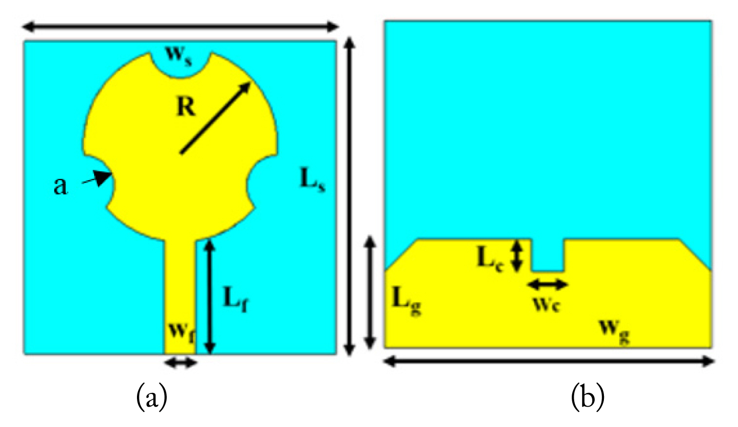
Design geometry of proposed antenna: (a) top view (b) bottom view.
Partial ground planes with specially designed slots and circular cuts in the radiating patch play a key role in obtaining UWB behavior. Mostly, partial ground planes decrease the energy kept in the substrates. The decrease of energy stored in the substrates causes a reduction in the Q-factor. As the Q-factor decreases, the bandwidth increases [34]. A thicker substrate is essential for improving the radiating power, reducing the conductor loss, and enhancing the impedance bandwidth of the antenna, which is related to the thickness (h) of a substrate. Therefore, to enhance the bandwidth of a radiating patch, the substrate’s thickness is increased and is given by Eq. (4).
2. Design Methodology
The overall design process to obtain the final optimized antenna consists of three stages, as illustrated in Fig. 2(a)–2(c). In the first stage, a circular-shaped patch antenna is obtained using the well-established equations [33]. The ground layer at the back side of the substrate is partial, as shown in Fig. 2(a). The circular antenna resonates for the wide frequency band ranging from 3–12 GHz, as depicted by the reflection coefficient results in Fig. 2(d), with a slight mismatch at 8 and 9 GHz. This antenna attains a peak gain value of 5 dB for the resonant band, as illustrated in Fig. 3. In the next stage, a circular-shaped patch is cut at the upper edge, such that the design evolves into a slotted circular-shaped antenna, as shown in Fig. 2(b). Table 2 depicts various design parameters and their dimensions in mm. The effective radius (Re) of the circular patch antenna can be calculated with Eq. (5) [33].

(a–c) Stepwise antenna design progress (d) simulated reflection coefficient for all design steps.

Simulated gain of antenna designs, Steps (1–3).

Detailed physical dimensions of the proposed antenna and FSS unit cell
Here, H is the thickness of the substrate, ɛr is the dielectric constant of the substrate, and R is the physical radius of the circular patch, which could be calculated in terms of resonant frequency using the following relation [33].
where F can be estimated using the following equation.
This antenna attains an impedance bandwidth of 3–12 GHz, with a little mismatch at 8 and 9 GHz. In addition to bandwidth, the peak antenna gain attained is 5 dB. Later, the design is modified by etching two more circular slots at the antenna’s sides, as well as one rectangular and two triangular slots in the ground layer, as shown in Fig. 2(c). It is noted that the antenna gain further enhances to 5.3 dB. In addition, the impedance matching improves as the reflection coefficient curve slightly shifts toward lower values, as shown in Fig. 2(d).
The surface currents on the antenna surface and ground plane at 10.6 GHz are depicted in Fig. 4(a). It is observed that the maximum currents are distributed along the antenna feed line and uniformly spread at the bottom edge of the radiating patch. Fig. 4(b) shows that the real part of the impedance parameter is almost equal to 50 Ω, and the imaginary part is 0 Ω at 10.6 GHz.
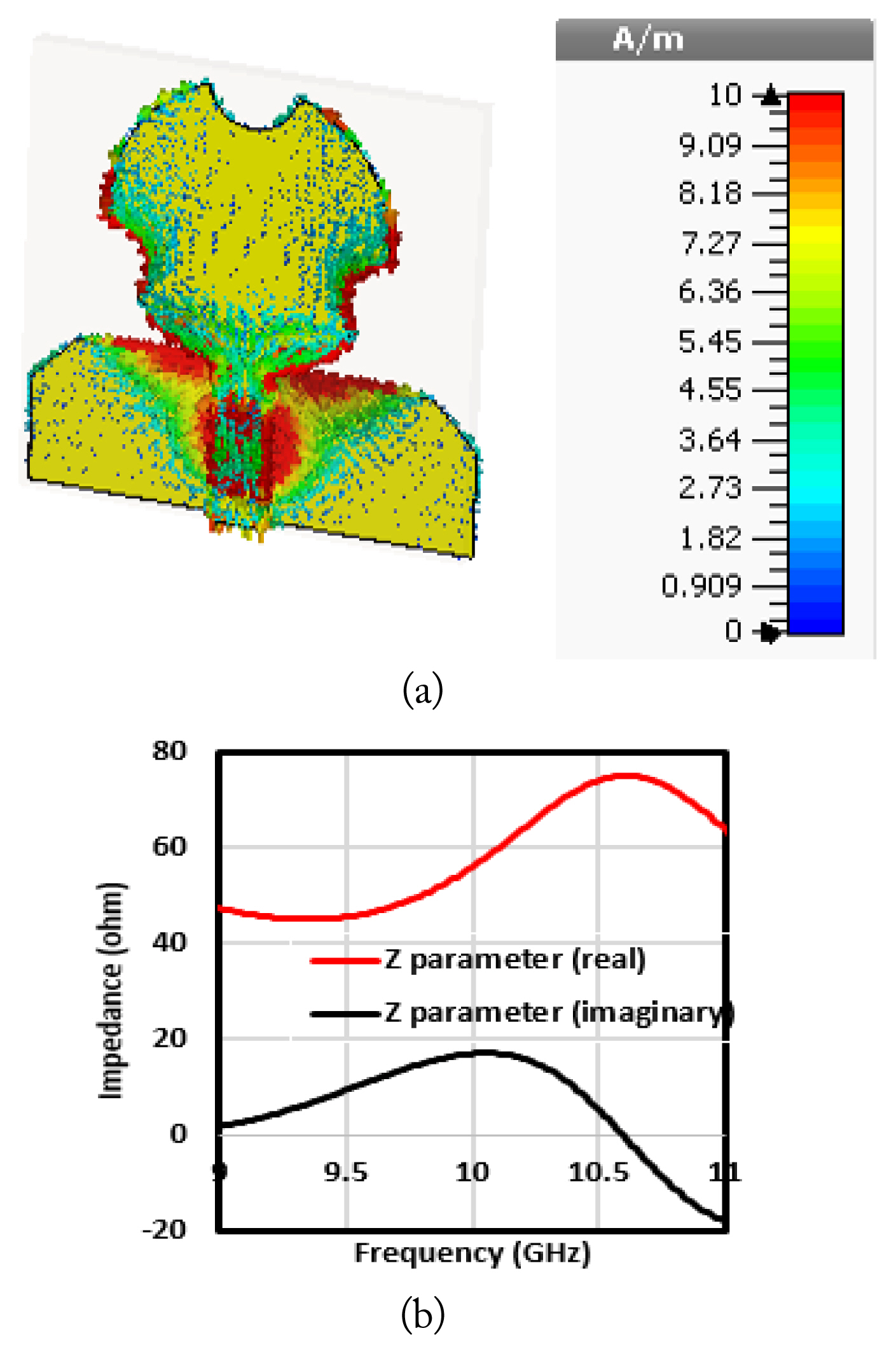
(a) Surface current distribution (b) impedance parameter of antenna at 10.6 GHz.
3. Parametric Analysis of Small Round Cuts
The antenna consists of a circular patch with round cuts at the edges, with a radius “a”. The round cuts have an effect on the reflection coefficient and gain of the proposed antenna. The parameter “a” has an effect on the antenna performance if its value is changed from 3 mm to 9 mm. Its reflection coefficient and gain vary, which are shown in Figs. 5 and 6, respectively. It is observed from the plots that a good impedance bandwidth can be achieved with a maximum gain of 5.1 dB for a = 3 mm.
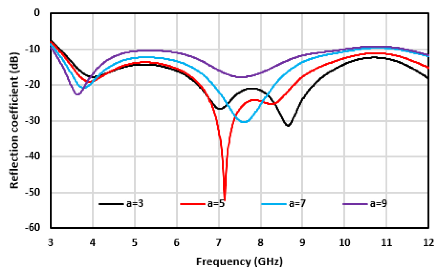
Effect of “a” on the antenna reflection coefficient.
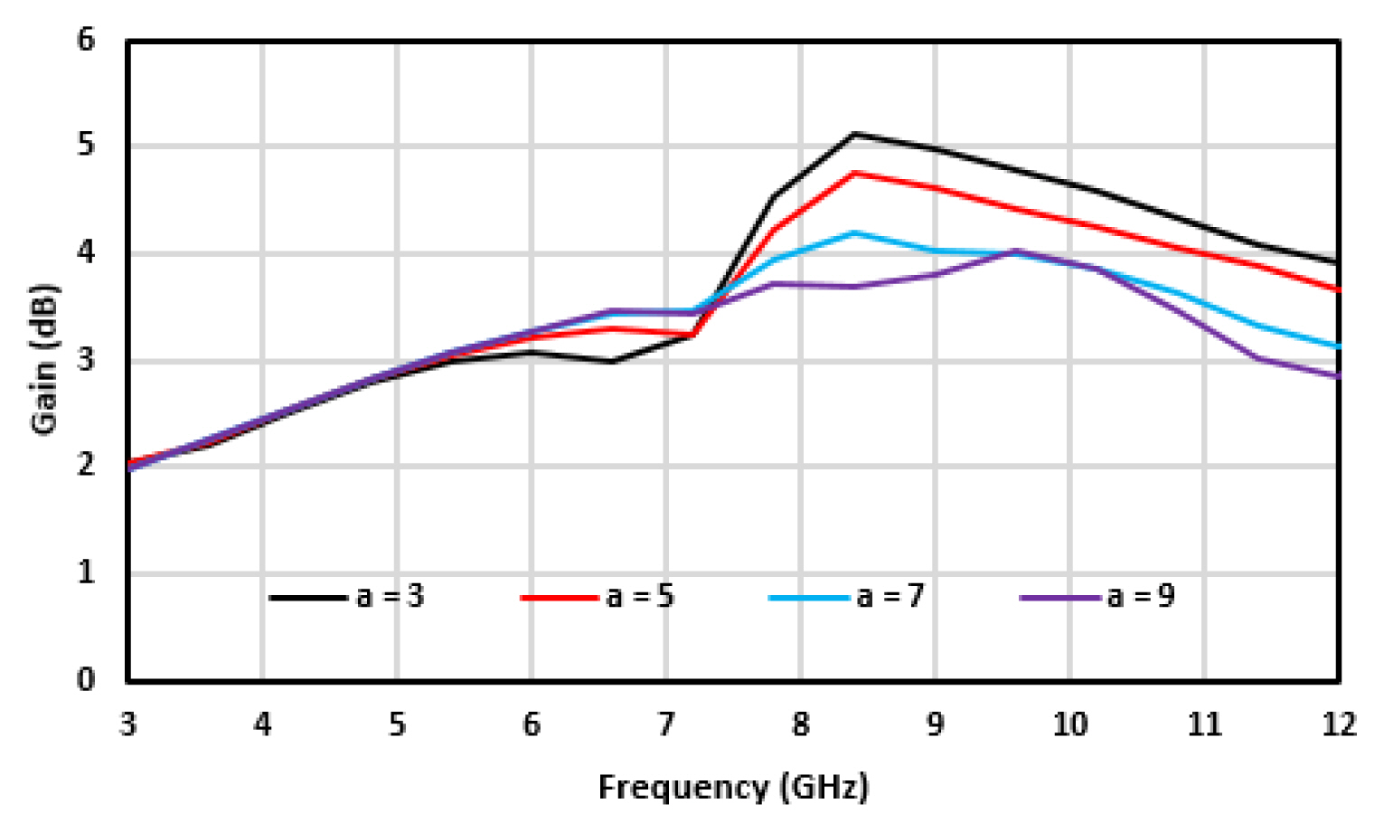
Effect of “a” on antenna gain.
III. Design of Frequency-Selective Surfaces (FSS)
1. Unit Cell Design
FSS are used as metallic reflectors made from periodic unit cells. The unit cells are arranged either in one dimension or two dimensions. The radiation characteristics of FSS depend on the shape, size, and space between two adjacent unit cells. The structure of the reported unit cell is depicted in Fig. 7(b). The unit cell is designed on a low-cost FR4 substrate with a relative permittivity (ɛr) of 4.3, tangent loss (tanδ) of 0.02, a thickness of 1.6 mm, and planner dimensions of 0.11λ × 0.11λ. The design of the unit cell is carried out in CST Microwave Studio (CSTMWS). The unit cell is designed through the steps shown in Fig. 7(a). In Step 1, a complementary loop structure (CLS) is formed, which gives a bandwidth of 3 GHz (i.e., from 3 GHz to 6 GHz), as shown in Fig. 7(d). In Step 2, the unit cell is modified to a complementary double loop structure (CDLS), which gives two resonances at 4 GHz and 11.5 GHz without attaining a UWB bandwidth. In Step 3, the inner and outer circular loops are connected horizontally, forming a CDLS connected horizontally (CDLSCH) and attaining a wide bandwidth of 6.6 GHz (i.e., from 3.2 GHz to 9.8 GHz). Finally, the inner and outer circular loops are connected horizontally and vertically, forming a CDLS connected horizontally and vertically (CDLSCHV). This increases the bandwidth of the unit cell, creating a stop band for the whole UWB bandwidth of 7.6 GHz, from 3.3 GHz to 10.8 GHz, as presented in Fig. 7(d). Fig. 7(b) is the design geometry of the unit cell, and Fig. 7(c) depicts the port assignment and boundary conditions to excite the unit cell. The parametric values of the optimized unit cell are provided in Table 2.
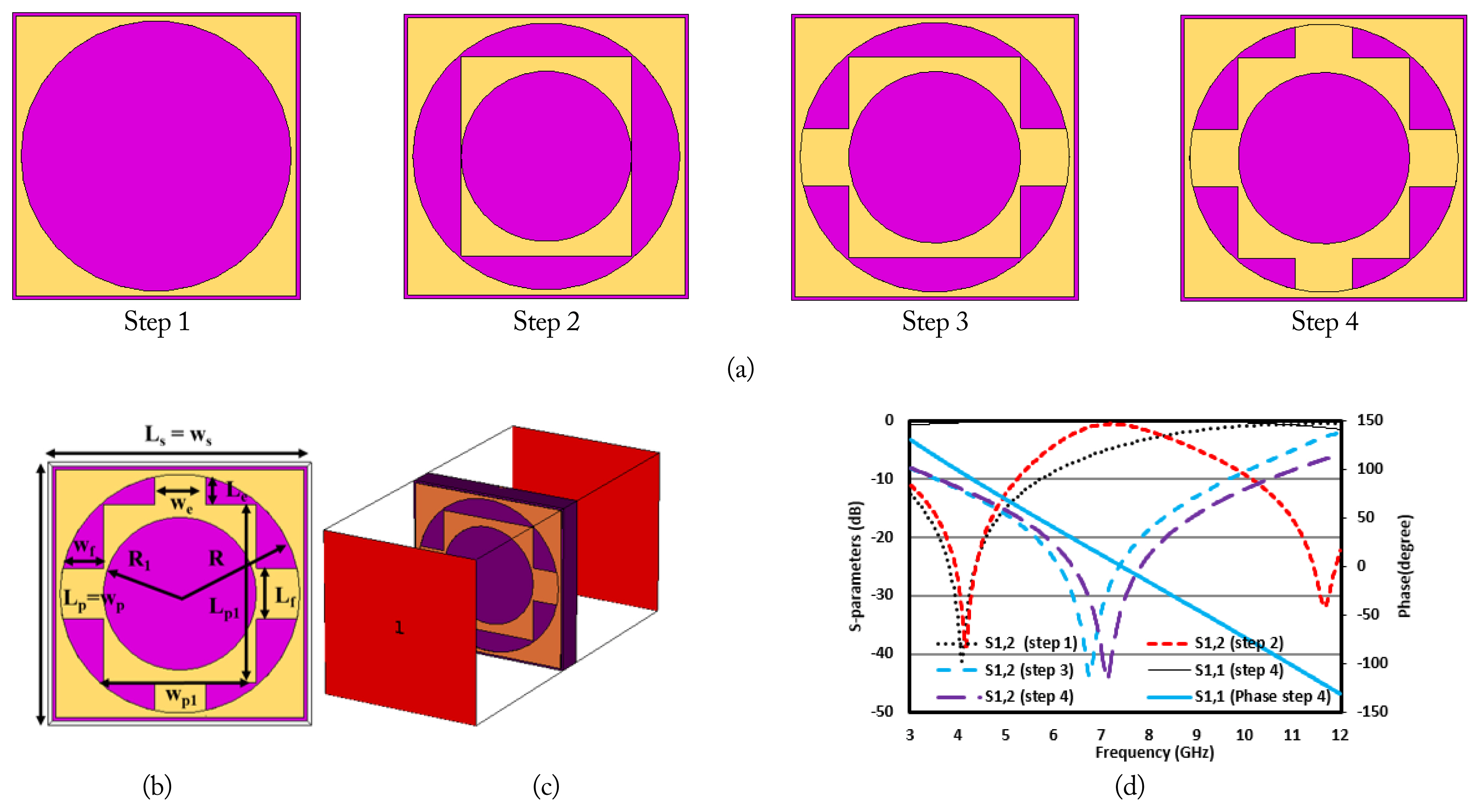
(a) Unit cell steps, (b) proposed unit cell, (c) unit cell excitation, and (d) S-parameters of the unit cell.
2. EC Model of the Unit Cell
An equivalent circuit model of the reported unit cell is modeled through the Advanced Designed System (ADS) simulator, followed by the simulation in the frequency range from 3 GHz to 12 GHz. The EC model is a simple and fast FSS unit cell analysis method. The basic shape of the FSS unit cell is a square loop, which is equivalent to the capacitor-inductor series circuit [35]. The values of capacitors represent the spaces among the adjacent conductors, while the values of inductors represent the conductive loop in the unit cell. Fig. 8(a) shows the ECM of the FSS unit cell designed in Step 4 of Fig. 7(a). The equivalent inductance and capacitance of the circuit can be calculated according to Eqs. (8) and (9) [36].
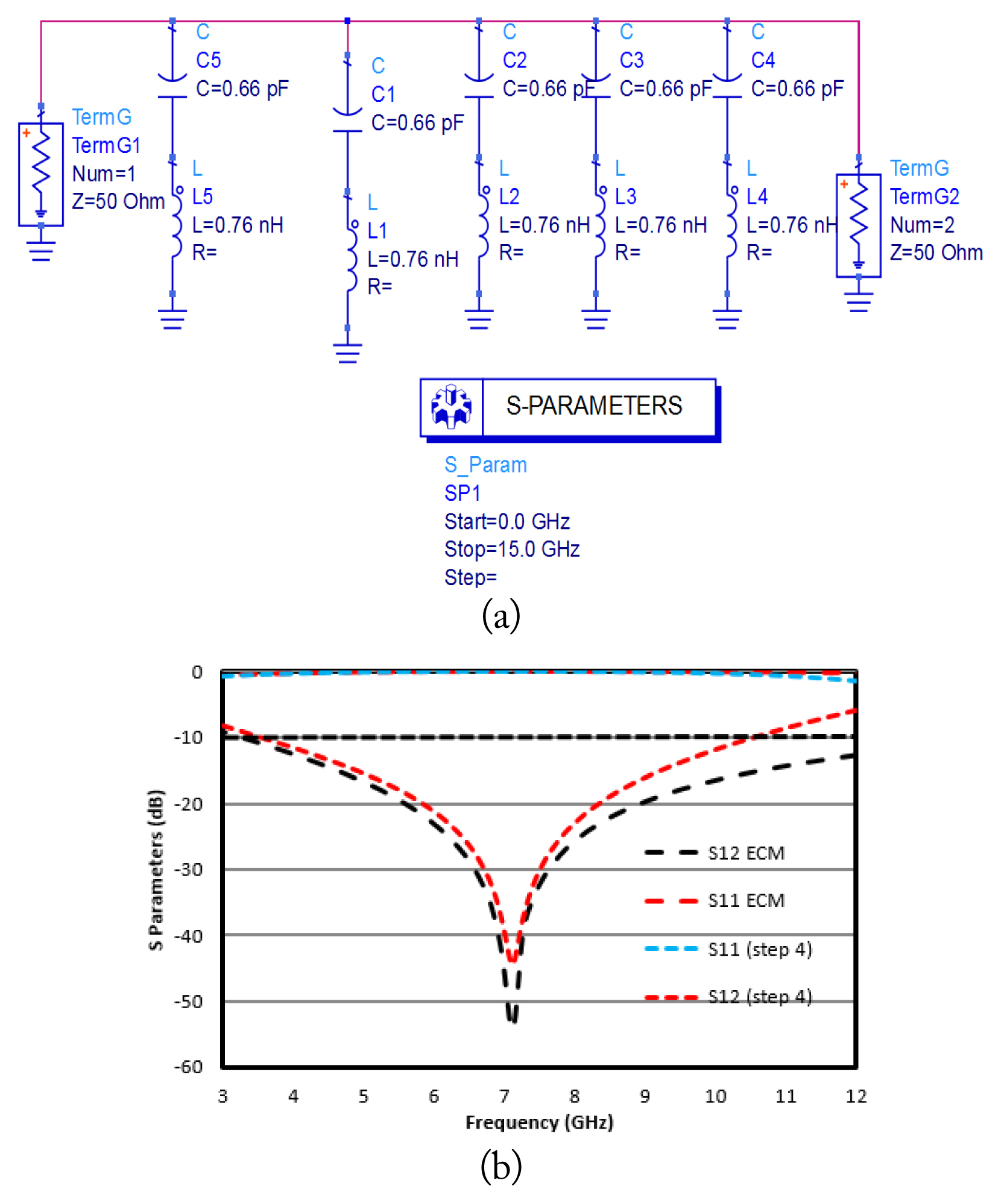
(a) EC model of the unit cell and (b) S-parameters of the unit cell.
By adjusting the values of capacitors and inductors, the reflection coefficient (S11) of the unit cell can be varied. Lastly, Fig. 8(b) shows simulated transmission coefficients of the reported unit cell in ADS, which agrees with the results in Fig. 7(d) using CSTMWS.
IV. FSS-Loaded Antenna
1. Performance Analysis
The geometrical configuration of the final proposed antenna loaded with FSS is shown in Fig. 9. The final proposed FSS consists of 36 elements arranged in a 6 × 6 array (rows × columns) along with the antenna placed above it at height S. The substrate used for this FSS structure is FR4 with 1.6 mm thickness. The overall size of the FSS is 62.5 mm × 62.5 mm × 1.6 mm. To obtain the optimal antenna performance, an investigation is conducted on the effects of varying the FSS array size on the antenna performance. The analysis is conducted for different array arrangements, with 4 × 4, 5 × 5, and 6 × 6 unit cell elements, as shown in Fig. 9(a). It is observed that the antenna shows good performance with a 6 × 6 FSS array, as evident by the reflection coefficient plots illustrated in Fig. 9(b), demonstrating an improved impedance match. In addition, Fig. 9(c) depicts that the antenna gain also improves with an increasing number of unit cells, where a peak gain of 8 dB is obtained for a 6 × 6 element array.
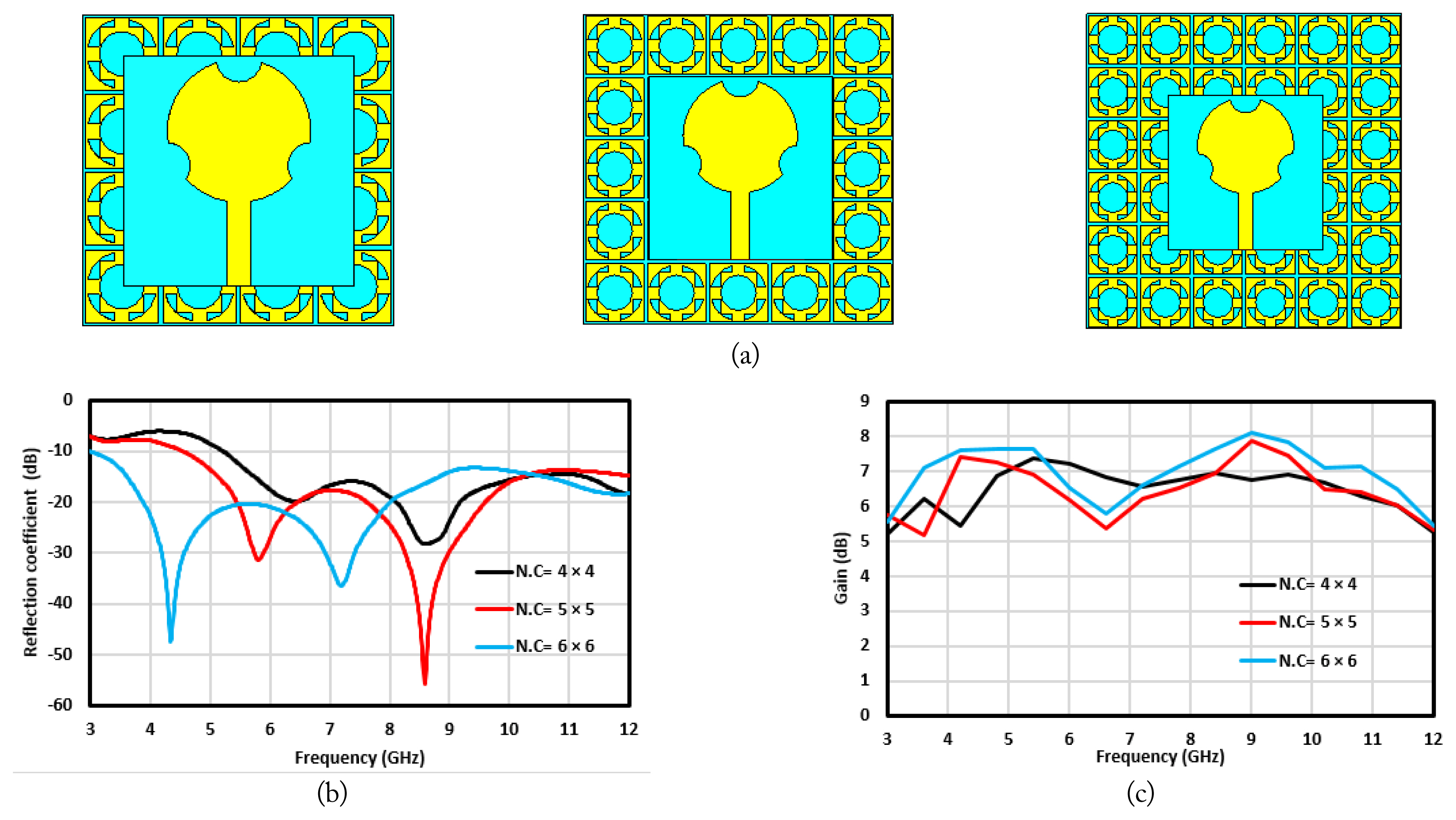
(a) Different FSS array configurations, and (b, c) reflection coefficient and simulated antenna gain for different FSS arrays at same distance of 10 mm.
In this work, the FSS is placed underneath the antenna so that the antenna’s radiation coming in the backward direction gets reflected. If the reflected waves by FSS and the radiations by the antennas are in phase, then the antenna gain enhances. In this scenario, an important factor is the spacing between the reference antenna and the FSS layer, which ensures the constructive interference of directly radiated and reflected waves. To estimate the spacing between the FSS and the antenna, the following equation is used [31].
where, n = … −1, 0, 1 …
Here, ϕFss represents the reflection phase of the FSS layer, S is the gap between the antenna and the FSS, and β is the open space propagation wave constant. The spacing between the antenna and the FSS layer must be an integer multiple of the wavelength at the central frequency. However, due to the wide-band nature of FSS, the gap between the FSS layer and antenna is optimized such that the maximum gain is achieved. Therefore, a parametric investigation is conducted for the gap between the antenna and the optimized FSS layer with a 6 × 6 element array. For the initial distance of 7 mm, the reflection coefficient is above −10 dB, and a little mismatch and peak gain of 9 dB is obtained, as shown in Fig. 10. Whereas, for the gaps of 10 mm and 15 mm, the antenna reflection coefficient is below −10 dB, but gain reduces with maximum values of 8 dB and 7.5 dB at 9 GHz. Hence, it is noticed that antenna gain is maximum at a spacing of 7 mm between the FSS and the antenna, with a mismatch at lower frequencies. Thus, the final proposed design with optimal performance is a UWB antenna with a 6 × 6 FSS layer placed below the antenna at a distance of 10 mm.
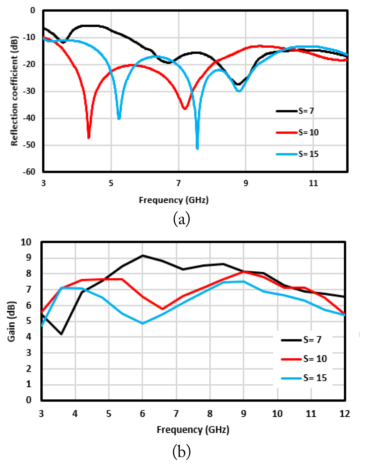
(a) Simulated reflection coefficient with various spacings and (b) simulated gain with various spacings.
V. Measurements of FSS-based UWB Antenna
To validate the performance of the proposed antenna, a prototype is fabricated, as shown in Fig. 11, and measured experimentally. To measure the prototype, polystyrene foam is placed between the antenna and the FSS to hold the antenna in place and provide adequate spacing between the antenna and the FSS. Polystyrene foam is organic plastic dielectric, which supports high frequencies of 106–107 Hz and is more resistant than other insulators. Besides providing insulation, it has low water absorption and is resistant to cracking [37]. The VNA Network Analyzer N5224A is used to measure the S-parameters of the antenna, whereas the far-field characteristics are measured in the anechoic chamber at the National University of Science and Technology (NUST). The measured results obtained are generally well matched with the simulated results. However, a few discrepancies were observed due to imperfections in fabrication and tolerance in the measurement setup.
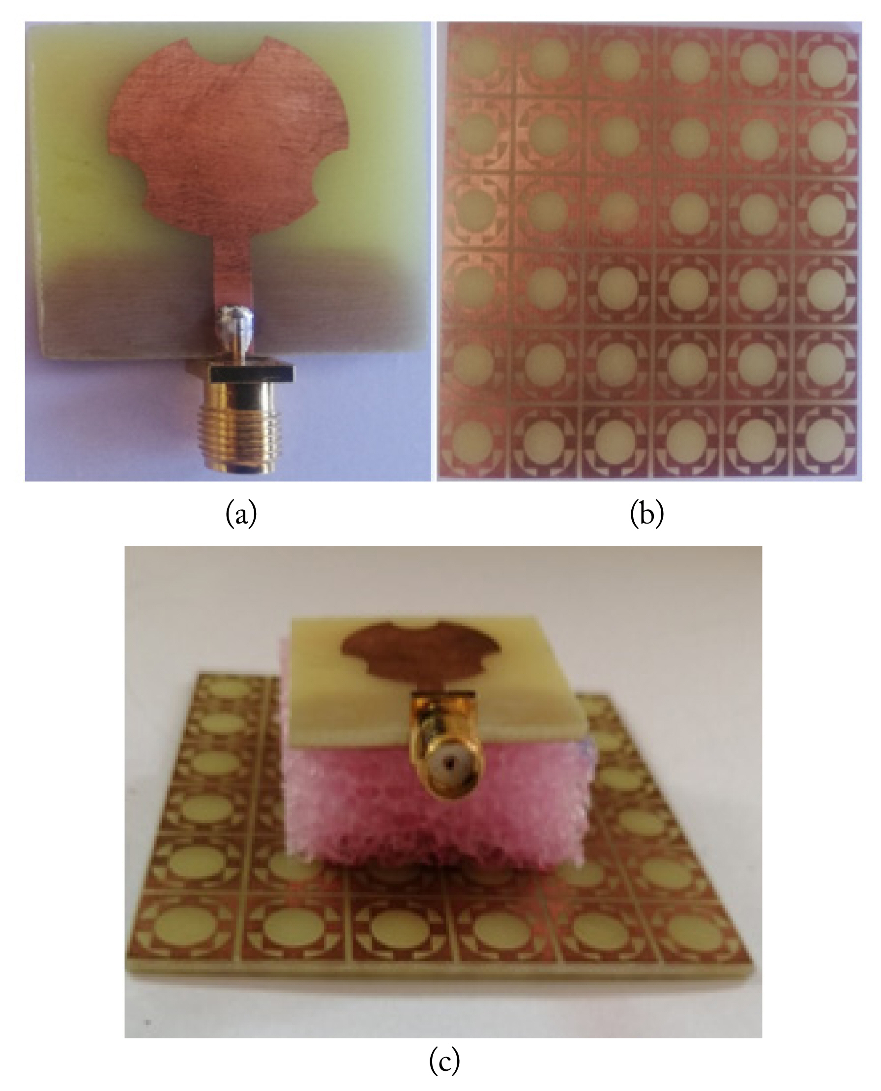
Fabricated prototypes: (a) UWB antenna, (b) FSS reflector, and (c) UWB antenna with FSS reflector.
1. Reflection Coefficient and Gain
Fig. 12 shows the simulated and measured reflection coefficient (S11) of the antenna with and without FSS configurations. The measured results of the proposed antenna without FSS demonstrate that the antenna shows good impedance matching and resonates for the frequency band ranging from 3–12 GHz, thus covering the UWB. Moreover, when the antenna is measured with the FSS placed below it, a slight upward and minor forward shift is observed for the obtained band ranging from 3.3–12 GHz. However, the obtained band still covers the UWB. Fig. 13 shows the simulated and measured gains for the antenna alone and the antenna combined with FSS. There is a significant improvement of at least 2.5 dB in gain when FSS is placed underneath the antenna. The gain of the proposed antenna is increased from 3 dB to 8.1 dB at 9 GHz by placing the antenna on the FSS. It is also noted that the measured and simulated results have good coherence and insignificant differences that occur mainly due to fabrication errors and tolerance in the measurement equipment and setup.
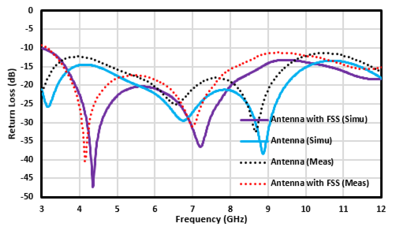
Simulated and measured reflection coefficient (S11) of the UWB antenna alone and with FSS.

Simulated and measured gain (dB) of the UWB antenna alone and with FSS.
2. Surface Currents and Efficiency of FSS-based Antenna
Fig. 14 shows the surface currents distribution on the metallic conductor at different frequencies to investigate the reflection phenomena of the reported metallic reflector with the radiating patch. However, it is noticed that the surface currents are strong at the feed and sides of the radiating patch. It is also observed that a moderate amount of current is distributed on the FSS surface and is simulated at 3.7 GHz and 8.5 GHz. In addition, it is observed that if the frequency is increased, the radiation becomes more directive, and the gain of the radiating element also increases. Due to the increase in gain, the antenna’s efficiency also improves, and its maximum efficiency is attained at 9 GHz, which is 80%. When FSS are employed, the antenna efficiency improves and reaches 87% at the same frequency. Finally, the comparison of the simulated results with the measured ones shows close agreement, as depicted in Fig. 15.

Simulated surface current of the proposed FSS-based UWB antenna at (a) 3.7 GHz and (b) 8.5 GHz.
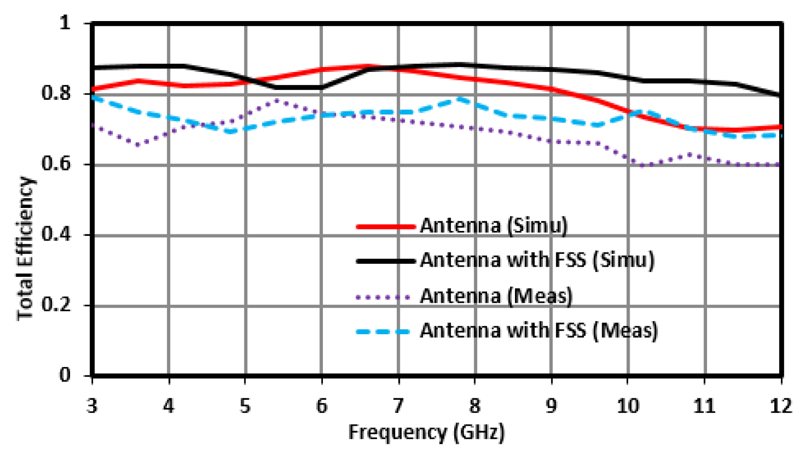
Total efficiencies of the proposed antenna with and without FSS.
3. Far-Field Results
The far-field measurements are obtained in the anechoic chamber. Fig. 16(a)–16(d) demonstrates the simulated and measured radiation patterns for E- and H-planes at 3.7, 5.7, 7, and 8.5 GHz. It is observed that for all selected frequencies, the antenna exhibits a bidirectional radiation pattern, whereas an omnidirectional radiation pattern is obtained for the principal H-plane. The simulated and measured results show good agreement.
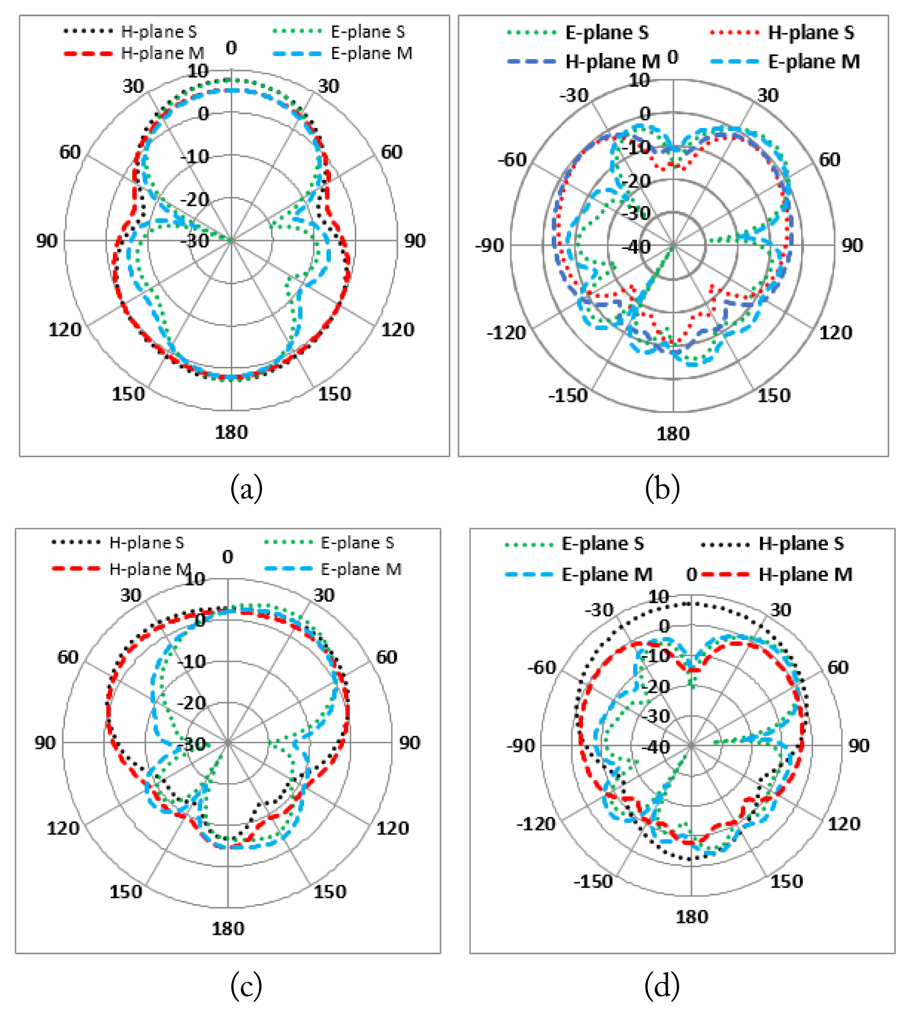
The 2D plots of FSS-based UWB antenna at (a) 3.7 GHz, (b) 5.7 GHz, (c) 7 GHz, and (d) 8.5 GHz.
VI. Literature Review and Table Discussion
An aperture-type FSS with an arrangement of 12 × 12 unit cells and its resonant features are studied in [38]. A resonant cavity patch is designed by the ground plane substrate and the metallic reflector superstrate. The reported FSS has reflective characteristics to improve the performance of the cavity antenna.
The operational bandwidth and gain are increased by 0.66 GHz and 8.5 dB, respectively, at an optimized spacing of 17.6 mm between the FSS superstrate and the radiating element. A compact single-layer and dual-layer FSS is designed, and its passband resonant characteristics are studied in [39]. It is then optimized for the spacing between the dual-layer FSS and simulated with a 31 × 31 unit cells array. In [40], an elliptical patch antenna is excited by slotted microstrip-feed resonates at 5.38 GHz. The antenna is then placed on the FSS with reflective behavior to enhance the proposed antenna’s performance. After the employment of the FSS at a specific distance of 28.5 mm, the gain is improved up to 5.1 dB, with a 0.13 GHz bandwidth. Nakmouche et al. [41] reported the improvement of gain through the FSS employed at the back of the proposed antenna using machine learning technology for 5G communications. The work in [42] is devoted to FSS to enhance the gain of the reported antenna and improve the overall radiation characteristics of the monopole UWB antenna through different FSS structures. A new technique called the squirrel search algorithm (SSA) is introduced in [43] to measure the accurate length and width of the FSS-based UWB antenna. The SSA enhances the accuracy of the antenna’s performance parameters to reduce bandwidth interference and attain uniform gain within the whole band. In this technique, patch antenna geometry is selected and simulated with FSS in numerous iterations. The UWB antenna acts as an impulse radar in [44], which is one of the key applications of UWB technology i.e., ground-penetrating radar (GPR).
GPR communication consists of transmit and receive antennas. The transmit antenna sends impulses to scan the object buried in the soil, which are responded to by the receive antenna. For reliable GPR communication, the UWB antenna has a compact size, lightweight, high efficiency, broad impedance bandwidth, flat variation gain, and minimal dispersion. Slot type, TEM horn, log periodic, bow-tie, rugby ball, Vivaldi, and valentine antennas are good candidates for GPR communication [45]. An experimental setup for GPR application consists of a cardboard filled with sandy soil and a thin aluminum foil at the back end [46]. A compact circuitry of the printed antenna is presented in [47, 48], inspired by metamaterial to enhance the gain and bandwidth. The metamaterial is designed on a flexible INP substrate from a Hilbert-shaped unit element, with a partial bottom plane with repeated slits to improve the bandwidth of the proposed antenna used for RF energy-harvesting applications. A metamaterial-based printed microstrip antenna excited by an exponential tapered coplanar waveguide (ETCPW) is reported in [49, 50]. In the small space between the FSS and UWB antenna, there is a mismatch of phase between the incident and reflected signals. The FSS consists of a dual layer on the FR4 substrate, with a non-linear response over the UWB range [51]. To improve the antenna’s gain, a dual-layer FSS is introduced to obtain a UWB stop response. The FSS has small dimensions compared to multilayer FSS [52]. Majidzadeh et al. [53] presented a reconfigurable FSS for UWB applications. The reported unit cell consists of two layers. The upper and back layers are printed on the FR4 substrate with dimensions 0.11λ × 0.11λ [53]. In [54, 55], a dual-layer FSS for UWB stop applications is presented. Both layers are the patch type of FSS with slits for miniaturization and are cascaded with space between them. The proposed unit cell’s dimensions of 0.2λ × 0.2λ give a transmission coefficient (S12) below −10 dB, which ranges from 4–7 GHz, with 56% bandwidth. A uniplanar FSS composed of periodic unit cells with size 0.14λ × 0.14λ improves the gain to 8.9 dB [56]. A multilayer FSS reflector is reported for gain augmentation of the UWB antenna without affecting the impedance bandwidth in [57]. An average increase in gain from 4 dB to 9.3 dB with a very large size is reported (Table 3).

Parametric comparison of the literature that used the FR4 substrate
VII. Conclusion
In this paper, a new UWB frequency selective surface microstrip-fed circular monopole antenna was presented and validated through measurements. The antenna covers a UWB bandwidth ranging from 3.2 to 12 GHz and achieves a maximum gain of 5 dB at 9 GHz. To improve the proposed antenna’s gain, the FSS is used, which improves the gain to 8 dB at the same frequency. The final FSS comprises a 6 × 6 array of unit cells. The dimensions of the unit cell are 0.11λ × 0.11λ at the lowest operating frequency of 3.3 GHz. It attains a stop band of 7.5 GHz from 3.3 to 10.8 GHz. The FSS-based antenna gives an ultra-wide stop band response over the entire band with a single FSS layer. The gain-enhancing ability of the FSS is experimentally established. The overall gain is 3 dB within the UWB band, and the maximum gain obtained is 8.1 dB at 9 GHz. Furthermore, some existing bands can be notched in the UWB spectrum, such as WiMAX, WLAN, and ITU bands, to avoid interference. Subsequently, the notches can be reconfigured to design a UWB antenna for WBAN applications and metamaterial-based UWB antennas for energy-harvesting purposes.
Acknowledgments
This research was funded by the Fundação para a Ciência e a Tecnologia, Portugal, under Grant No. UIDB/04111/2020 (COPELABS).
References
Biography

Iftikhar Ud Din received his B.Sc. and M.Sc. degrees in telecommunication engineering from the University of Engineering and Technology, Peshawar, Pakistan, in 2017 and 2021, respectively. He is pursuing a Ph.D. in telecommunication engineering from the University of Engineering and Technology, Mardan, Pakistan. His research interests include UWB antennas, FSS-based UWB antennas and Sub-6 GHz 5G antennas, 5G millimeter wave antennas and MIMO antennas, frequency selective surfaces, EBGs, and metamaterial-based antennas.

Waheed Ullah (SM’19) received his B.Sc. degree in electrical and electronics engineering from the University of Engineering and Technology Peshawar, Pakistan, and master’s degree in communication and information systems from Nanjing University of Aeronautics and Astronautics, China, in 2012. He has a Ph.D. from the University of the Witwatersrand, South Africa, in 2021. He is currently affiliated with SLTC, Sri Lanka. His research interests are in wireless communication systems and networks. His recent research includes NB-LDPC, SWIPT, coding-based secure communication, NOMA, and massive MIMO.

Nisar Ahmad Abbasi received his B.Sc. degree (with honors) in electrical and electronic engineering from the University of Engineering and Technology, Peshawar, Pakistan, in 2001, and his M.Sc. and Ph.D. degrees in electronic engineering from the University of Sheffield, Sheffield, UK, in 2007 and 2011, respectively. He has held various positions, such as assistant manager, manager, and general manager, while working for the Ministry of Science, Pakistan, between 2001 and 2016. He is currently an assistant professor at the University of Hafr Al Batin, Hafr Al Batin, KSA. His research interests include the design and analysis of various antenna types and telecommunication networks. Dr. Abbasi is a professional engineer (PE) in Pakistan and a member of the Pakistan Engineering Council (PEC).

Sadiq Ullah is a professor and head of the Telecommunication Engineering Department at the University of Engineering & Technology, Mardan, Pakistan. He is also the director of postgraduate studies at UET Mardan and head of the Antennas & Microwave Engineering Research Group (AMERG). Sadiq Ullah received his B.Sc. in electrical engineering from the University of Engineering and Technology, Peshawar, Pakistan. He achieved his M.Sc. in electrical engineering from the University of Engineering and Technology, Taxila, Pakistan. In 2007, he joined the Department of Electronic and Electrical Engineering at Loughborough University, U.K., and was awarded a Ph.D. for his research in the field of design and measurement of metamaterial-based antennas in 2010. He worked as an assistant manager (electronics) in a public sector R&D organization in Islamabad, where his main responsibilities were hardware, software co-design, design and testing of high-precision electronics, and test equipment. His research mainly focuses on the design and measurement of low-profile antennas on electromagnetic bandgap structures, metasurfaces, multiband antennas, wearable antennas, mmW/THz antennas, and 5G antennas. He has also worked as a research associate at Loughborough University, where he researched the propagation effects of rain, snow, ice, fog, and forest in millimeter wave bands. He has published his research in international conferences and Sci-Indexed journals.

Waleed Shihzad was born in Mardan, Pakistan, in 1994. He received his B.Sc. in telecommunication engineering from the University of Engineering and Technology, Peshawar, Pakistan, in 2017. He is currently pursuing his M.Sc. in telecommunication engineering from the University of Engineering and Technology, Peshawar, Mardan Campus, Pakistan. His research interests mainly focus on the design and analysis of high-gain THz antennas for space communication systems according to ITU recommendations, plasmonic antennas for high-speed electronics, and UWB and millimeter wave antennas.

Bilawal Khan received his B.Sc. in electrical engineering and M.Sc. in telecommunication engineering from the University of Engineering and Technology, Peshawar, Pakistan, in 2014 and 2019, respectively. Currently, he is studying for his Ph.D. in telecommunication engineering at the University of Engineering and Technology, Mardan, Pakistan. He previously worked as a supervisor in the renewable energy sector. He has also completed various diplomas and mastered soft skills from different institutes, including the University of California, Irvine, and Digiskills.pk. His educational research activities are mainly focused on the field of metasurfaces, metamaterials, polarization manipulation devices, microwave, and millimeter-wave technologies.

Dushantha Nalin K. Jayakody (Senior Member, IEEE) received his M.Sc. in electronics and communications engineering from Eastern Mediterranean University, Turkey (under the University Full Graduate Scholarship), and his Ph.D. in electronics and communications engineering from the University College Dublin, Ireland. From 2014 to 2016, he was a postdoctoral research fellow at the University of Tartu, Estonia, and the University of Bergen, Norway. From 2016 to 2022, he was a professor at the School of Computer Science and Robotics, National Research Tomsk Polytechnic University (TPU), Russia. He held visiting and/or sabbatical positions at the Center for Telecommunications Research, University of Sydney, Australia, in 2015 and Texas A & M University in 2018. He was a visiting professor within the framework of the Academy of Finland at the University of Jyvaskyla, Finland, in 2019 and 2022. He was also a visiting professor at the University of Juiz de Fora, Brazil, in 2019. Since 2022, he has been with COPELABS, Lusófona University, Lisbon, Portugal.