J. Electromagn. Eng. Sci Search

CLOSE


J. Electromagn. Eng. Sci > Volume 23(6); 2023 > Article
Li, Xue, Li, Chung, and Huang: A Wideband Differentially Fed Circularly Polarized Slotted Patch Antenna with a Large Beamwidth

Abstract

A wideband differentially fed circularly polarized (CP) antenna featuring a slotted patch design with a large beamwidth is presented. The final design of the differentially fed CP antenna, aimed at achieving high gain and a wide axial ratio (AR) bandwidth, involves coupling a differential bending dipole antenna to the slotted patch in the same plane. The presented differentially fed CP antenna demonstrates characteristics of a large AR beamwidth, as verified by simulation and experiment. The measured AR beamwidths of 132.3° in the xoz plane (phi = 0°) and 116.2° in the yoz plane (phi = 90°) are realized at 5.5 GHz. The measured result exhibits broadband performance with a −10-dB impedance bandwidth of 78.8% (3.81–8.76 GHz), a 3-dB AR bandwidth of 36.7% (4.78–6.93 GHz), and a maximum gain of 10.2 dBic.

I. Introduction

Circularly polarized (CP) antennas offer advantages over conventional linearly polarized antennas as they are more resilient against multipath fading and mitigate polarization-related issues. Therefore, CP antennas are widely utilized in modern wireless communication systems [1, 2]. However, the drawbacks of traditional CP antennas are their narrow axial ratio (AR) bandwidth and low gain. This has spurred a need to design a wideband high-gain CP antenna.
Single-layer CP patch antennas have a narrow AR bandwidth because of their high Q factor [3]. To overcome this limitation, techniques involving stacked patches and parasitic structures have been employed to extend the AR bandwidth [47]. For example, the introduction of notched stacked patches has enabled a single capacitive-fed patch antenna to achieve an AR bandwidth of 10% [4]. In [5], two-layer stacked patches coupled with a driven patch featuring a windmill slot configuration achieved wideband CP radiation. In addition, CP cross-dipole antennas have gained attention for their wide AR bandwidth and high gain characteristics [810]. Notably, a CP cross-dipole antenna designed for the Navigation Satellite System achieved an AR bandwidth of 41.3% [8]. In [9], an antenna composed of a cross-dipole and dual-cavity structure achieved unidirectional radiation and wide CP radiation. In particular, an excellent AR bandwidth of 90.9% was realized in [10]. However, cross-dipole antennas typically have a relatively high profile. Another type of single-fed patch CP antenna exhibits a wide 3-dB AR beamwidth (ARBW) and thus has a wide range of applications [1114]. The common methods to realize CP radiation and a wide 3-dB ARBW are modifications to rectangular patches, including the addition of four unequal circular patches [11], four bending stubs [12], or rectangular patches with four angled narrow slots [13]. In [14], a 3-dB ARWB of 190° was realized by four three-dimensional radiating patch elements connected by a four-port feeding network with a 90° phase difference. These wide ARBW CP antennas can be utilized for a variety of applications, such as global positioning systems; however, traditional wide ARBW CP patch antennas still often suffer from a narrow 3-dB ARBW.
Multi-feed is another conventional method for widening AR bandwidths. Two feeds with a 90° phase shift [15], three feeds with a 120° phase shift [16], and four feeds with a 90° phase shift [17] have been used to excite the same radiation patch to realize wideband CP radiation. In [18, 19], a wideband four-fed CP antenna array composed of four sequential rotated radiation patches and a four-way feeding network with a phase difference of 90° was designed. Multi-feed CP antennas can yield a broad CP bandwidth and high gain, but they have drawbacks such as a large structure size and complex feeding networks.
To further widen the AR bandwidth, metasurface antennas have been introduced and designed [2026]. In general, CP metasurface antennas can be excited by two methods: aperture-coupled feed [2023] and patch-coupled feed [2426]. In [20], a novel metasurface design utilized unit cells with two pin-loads in the diagonal direction to realize wide CP radiation. The feed system of the CP metasurface antenna in [23] was composed of a cross-slot and a bending microstrip feeding line. In [26], a metasurface-based CP antenna was coupled by a square patch with a tilted slot. Notably, the backward radiation of metasurface-based antennas with aperture-coupled feed is stronger, while the AR bandwidth of patch-coupled metasurface-based antennas is narrow.
Recently, some differentially fed antennas have been proposed in [27, 28]. These antennas, in contrast to conventional single-ended antennas, do not necessitate the use of redundant baluns or 180° hybrids. As a result, they are widely utilized in differential microwave circuits. In [29], the presented differentially fed CP antenna, which was designed to achieve a wide AR bandwidth, consisted of two cross-dipoles and phase shifters. In [30], a series-fed CP differential antenna, which utilized wideband phase shifters and crossed open slot pairs, realized a wide 3-dB ARBW.
In this paper, a wideband differentially fed CP slotted patch antenna is presented, and the linearly polarized differentially fed dipole antenna is bent for achieving CP radiation. Two centrosymmetric coupling patches and slotted patches are added in the simulation to the surface of the bending dipole antennas to further extend the AR bandwidth and impedance bandwidth. When the slotted patch is used, the final differentially fed CP antenna achieves high gain and wideband CP radiation. The measured result exhibits broadband performance with a −10-dB impedance bandwidth of 78.8% (3.81–8.76 GHz), a 3-dB ARBW of 36.7% (4.78–6.93 GHz), and a maximum gain of 10.2 dBic.

II. Antenna Design and Performance

1. Antenna Geometry

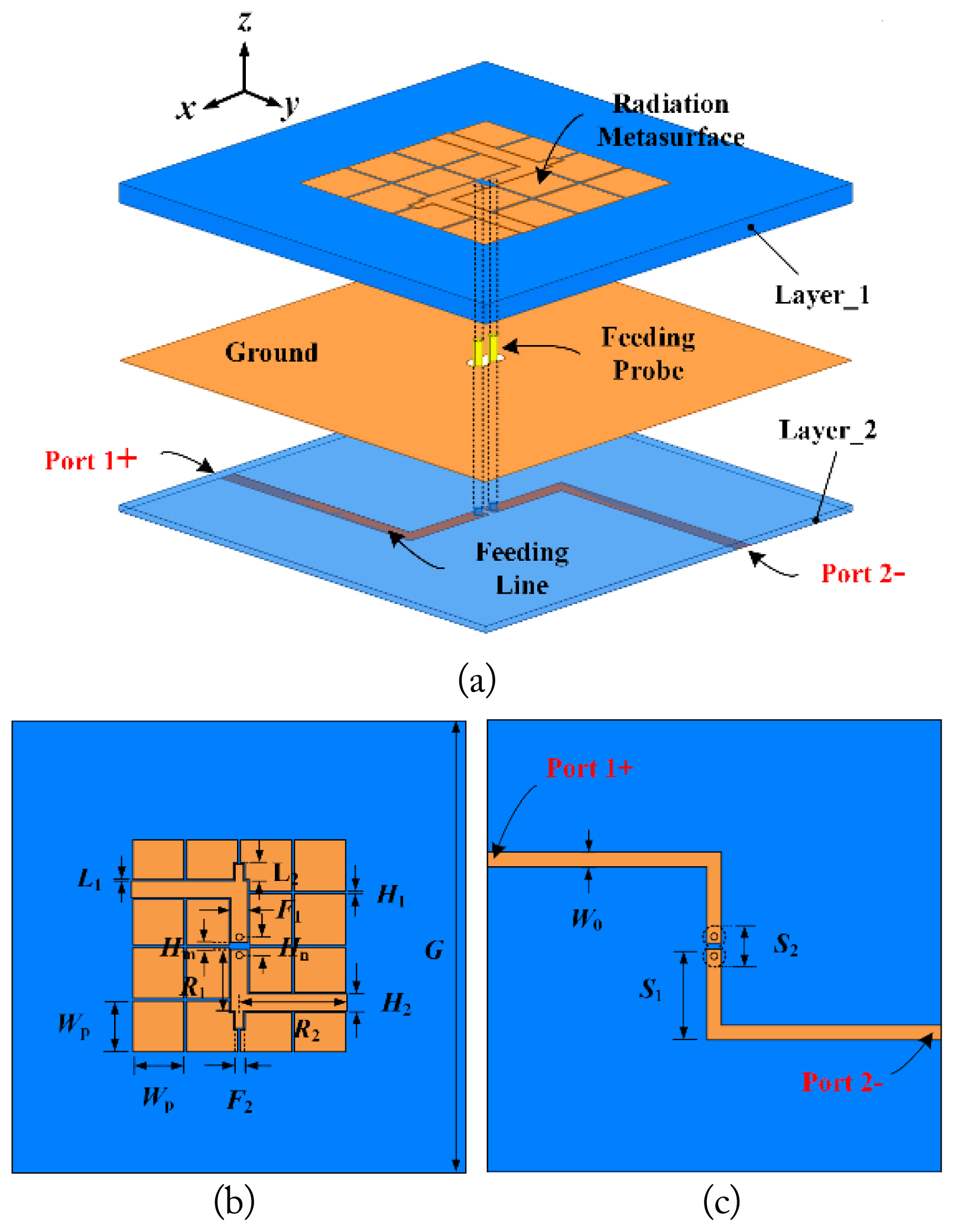
Fig. 1 shows the structure of the presented differentially fed CP antenna from various angles, including three-dimensional, side, top, and bottom views. The material of Layer 1 with a thickness (h1) of 3 mm is designated as F4BM, whose relative dielectric constant is 2.2 and the loss tangent is 0.0025. Material Rogers 4003C is utilized for Layer 2 with a thickness (h3) of 0.8 mm to reduce the antenna cost, whose relative permittivity is 3.55 and the loss tangent is 0.002. Fig. 1(b) shows the air gap (h2) between Layer 1 and Layer 2 with a thickness of 2 mm. The driven bending dipole and slotted patch are fabricated on top of Layer 1. The differential microstrip feeding line is fabricated at the bottom of Layer 2. The presented differentially fed CP antenna was optimized using Computer Simulation Technology (CST) Microwave software to determine the final parameters, resulting in the following values (in mm): L1 = 0.3, L2 = 3, Hm= 1.3, Hn= 3, H2 = 3, S1 = 11.3, S2 = 5, W0 = 1.8, F1 = 3, F2 = 1.5, F3 = 1.5, R1 = 9.35, R2 = 18, H1 = 0.5, Wp = 9, and G = 80.

2. Operating Principles and Analysis of Wideband CP Antennas

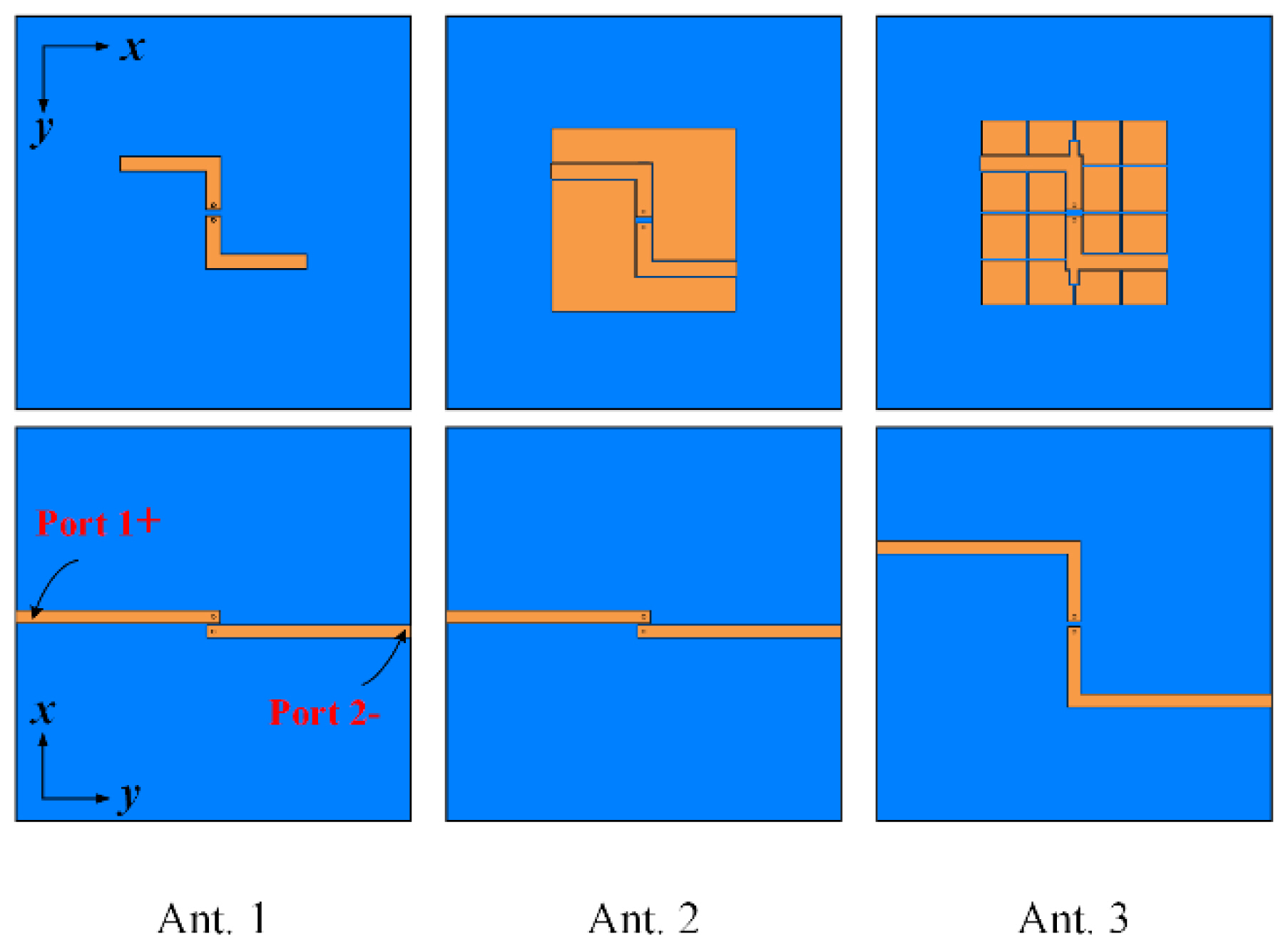
Three prototypes of differentially fed CP antennas are presented in Fig. 2 to illustrate the design process. The dimensions of the three antenna prototypes are the same as those of the original antenna.
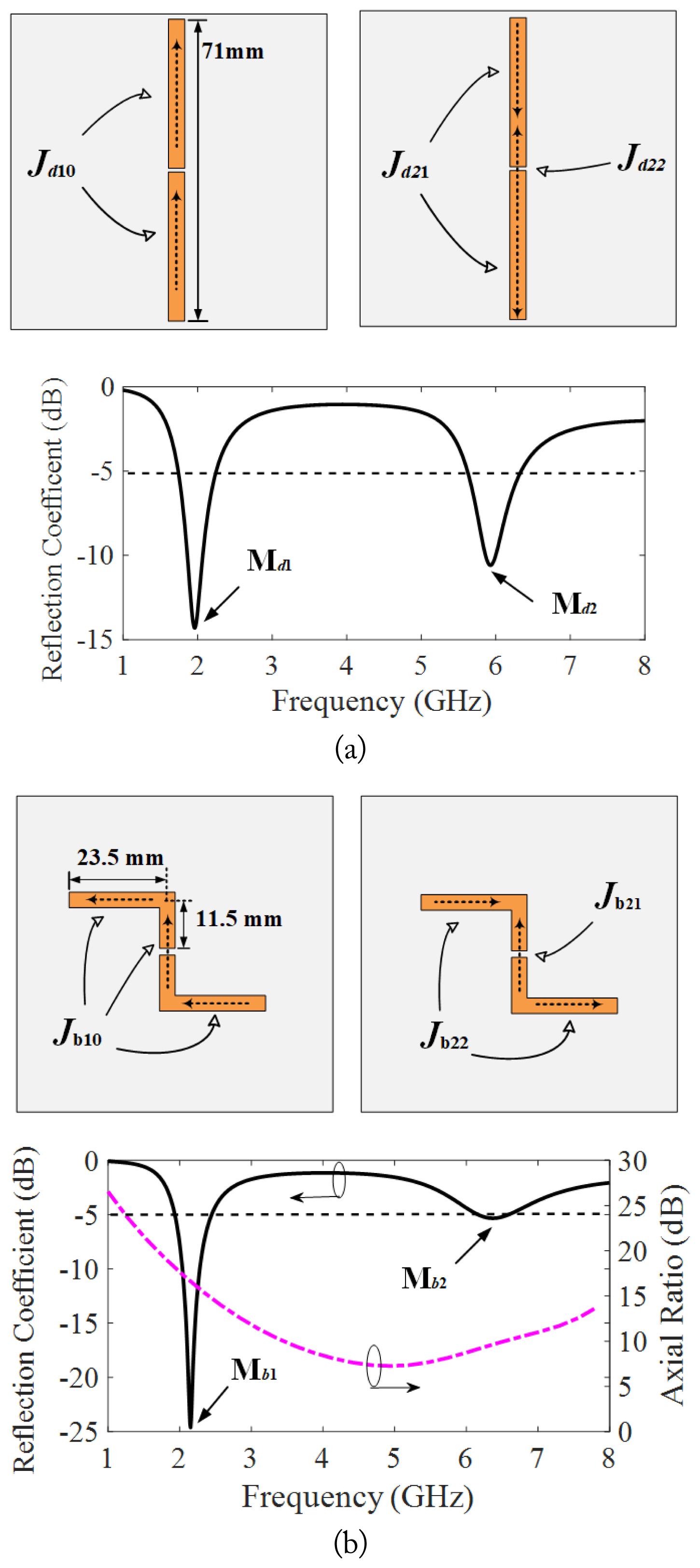
The conventional dipole antenna is bent to form Ant-1. To better investigate the principle of the bending dipole forming circular polarization and to determine the size of the bending dipole, the mode current and resonant frequency of the dipole in free space as well as the mode current, resonant frequency, and AR of the bending dipole in free space are given in Fig. 3. As shown in Fig. 4(a), the length of the dipole allows the first resonant frequency of the dipole, Md1, to be calculated around 2 GHz, and the corresponding mode current is Jd10. By observing the distribution of the mode currents Jd21 and Jd22 in the second mode, it can be found that the second resonant frequency is around 6 GHz.
The difference between the two mode currents of the conventional dipole is that the mode current Jd10 of Md1 is oriented in the same direction, while the mode currents Jd21 and Jd22 of Md2 are reversed. Fig. 4(b) shows the mode currents, resonant frequencies, and AR of the bending dipole in the free space, where the total length of the bending dipole is the same as that of the conventional dipole above. It can be seen that the current distributions of the newly formed mode currents Jb10, Jb21, and Jb22 are the same as before bending, and the changes in resonant frequencies of their corresponding Mb1 and Mb2 are also minimal. Since the first resonant mode Md1 of the conventional dipole corresponds to the current Jd10, which is oriented in the same direction, the corresponding current Jb10 of the bending dipole can generate orthogonal mode currents, but the 90° phase difference required for the formation of CP radiation cannot be generated. The second resonant mode Md2 of the conventional dipole corresponds to the currents Jd21 and Jd22, which are reversed, so the corresponding currents Jb21 and Jb22 of the bending dipole can produce a 90° phase difference by introducing a difference in the lengths of the horizontal and vertical radiating structures at one end of the bending dipole, approximately 0.25λ.
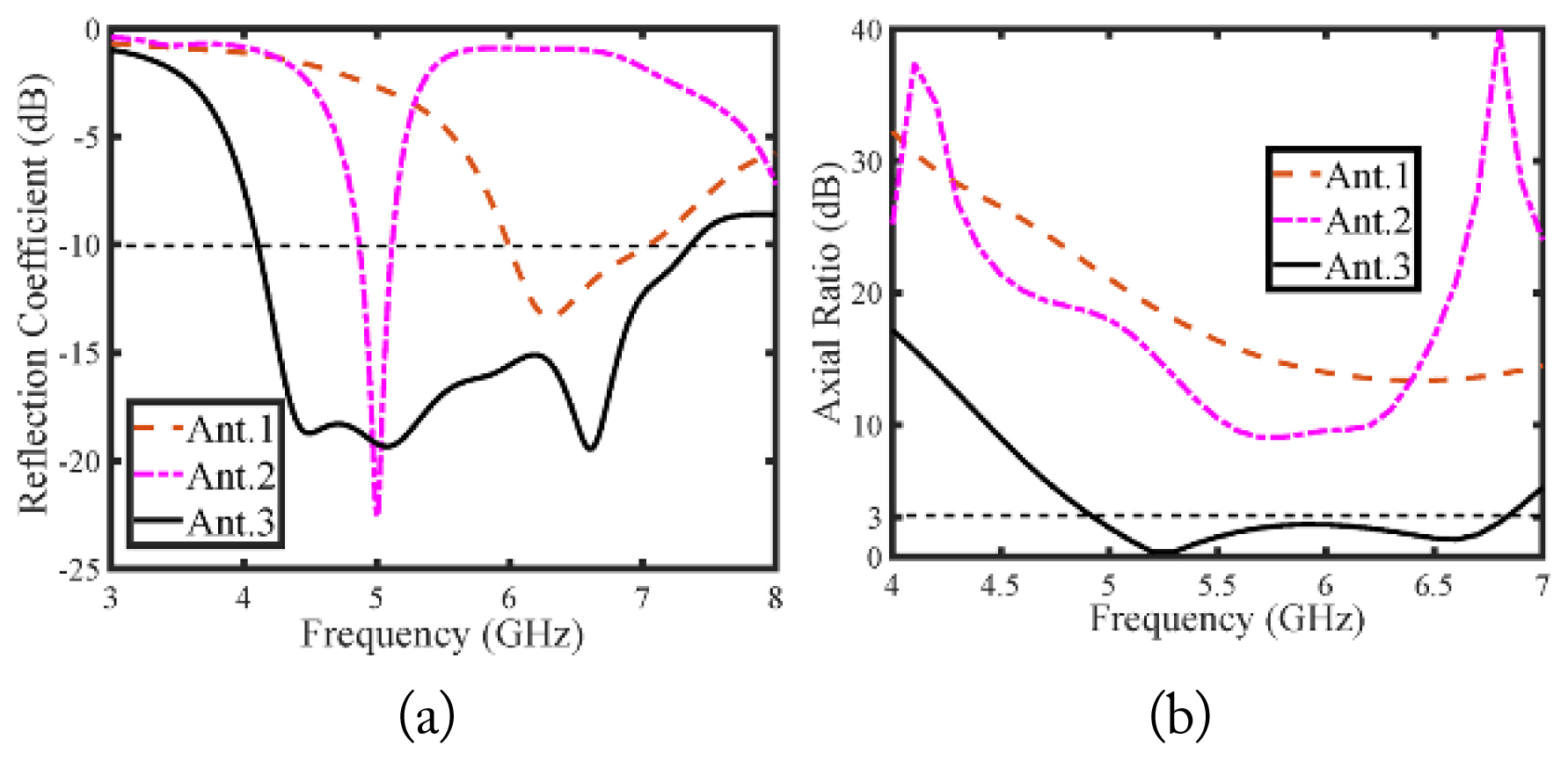
The AR of the final bending dipole in Fig. 4(b) changes considerably around 6 GHz. As mentioned above, dielectric and grounding plates are added to Ant-1 to obtain radiation in the broadside direction, as opposed to the bending dipole in free space. As shown in Fig. 2, the resonant frequency of Ant-1 is around 6 GHz and shows a tendency toward CP radiation, evident from the AR measurements around 6 GHz.
Ant-2 is formed by adding two asymmetric coupling patches to Ant-1 to extend the AR bandwidth. Fig. 2 shows that after adding the two centrosymmetric coupling patches, the resonant frequency of Ant-2 shifts to 5 GHz and AR is below 10 at 6 GHz. However, the AR of Ant-2 is no less than 3 dB in the desired bandwidth.
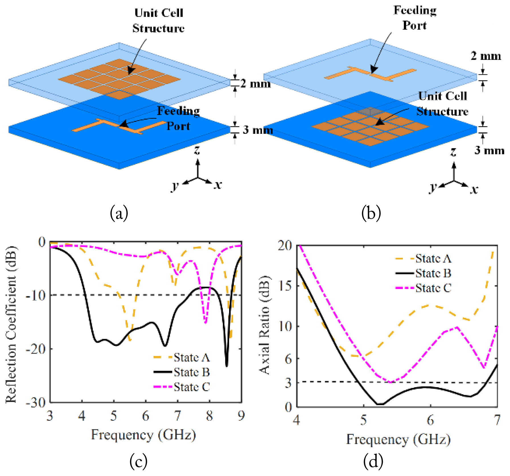
The final step is to achieve broadband CP radiation using a 4 × 4 unit cell radiation structure coupled by the bending dipole. This configuration was tested in three different states: state A, where the unit cell structure was placed on top of the bending dipole; state B, where the unit cell structure and the bending dipole were placed in the same plane (representing the final antenna design); and state C, where the unit cell radiating structure was placed underneath the bending dipole. A three-dimensional structure of states A and C, along with the reflection coefficients and AR for these three cases, is provided in Fig. 5. It is evident from Fig. 5(c) and 5(d) that the reflection coefficients and AR corresponding to states A and C do not achieve the desired broadband effect. Ultimately, the simulated −10-dB impedance bandwidth of 56.9% (4.1–7.36 GHz) and 3-dB ARBW of 32.3% (4.93–6.83 GHz) were achieved by placing the bending dipole in the same plane as the unit cell radiation structure (Ant-3).

3. Antenna Design Guidelines

The wideband differentially fed CP antenna was created through the following steps:
  • Step 1: Create a bending dipole with a total length of about 1.5λ0 at 6 GHz, which corresponds to 0.5λ0 at 2 GHz. Ensure that the difference in length between the horizontally radiating and vertically radiating structures at one end of the bending dipole (R2-R1) is about 0.25λ0.

  • Step 2: Add a ground plane to adjust the height of the ground plane and the bending dipole. Add asymmetric coupling patches and investigate whether the antenna can achieve broadband CP radiation by optimizing the dimensions of the structure.

  • Step 3: Add a 4 × 4 unit cell patch, placing it in the same plane as the bending dipole. Add a stub at one end of the vertical radiation structure of the bending dipole and adjust the length (L2). A wideband differentially fed CP antenna is then created.

4. Parametric Study

Parametric studies were conducted to determine the final dimensions. The performance of the presented differentially fed CP antenna is influenced by numerous parameters. In this study, the key parameter L2 was selected. Fig. 6 illustrates how the length L2 affects AR, with the reflection coefficient and ARBW being notably sensitive to changes in L2. This is because the length of L2 affects the current strength along the y-direction. Ultimately, a value of L2 = 3 mm was selected as the final size for the proposed differentially fed CP antenna.

III. Experiment Verification

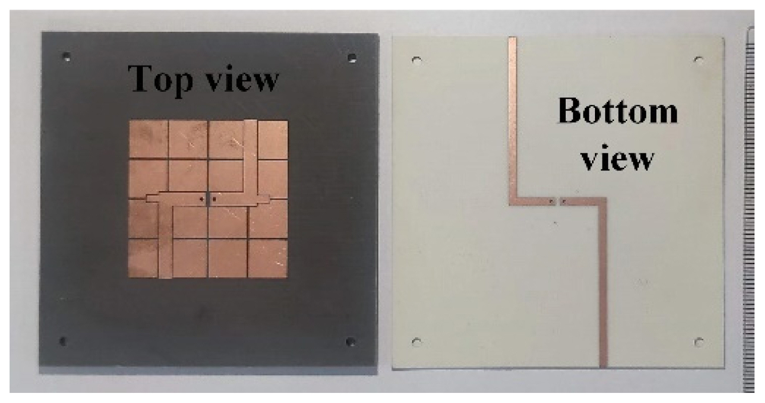
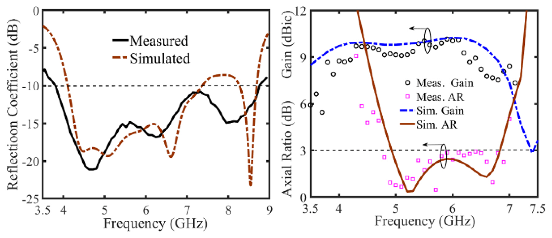
The prototype, as depicted in Fig. 7, was fabricated to validate the simulation results of the presented CP antenna. The Agilent N5062A network analyzer was utilized to measure the S-parameters. The anechoic chamber was used to test radiation characteristics, including gains and ARs. A power divider with a 180° phase difference was used in the tests. Fig. 8(a) shows that the simulated −10-dB impedance bandwidth is 56.9% (4.10–7.36 GHz) and the measured −10-dB impedance bandwidth is 78.8% (3.81–8.76 GHz). The difference between the measured and simulated reflection coefficient can be attributed to the idealized differential feed used in the simulation, where the amplitude and phase differences of each port are assumed to be equal across all frequency ranges, while, in reality, the power divider exhibits variations. Fig. 8(b) shows a simulated 3-dB ARBW of 32.3% (4.93–6.83 GHz) compared to a measured ARBW of 36.7% (4.78–6.93 GHz).
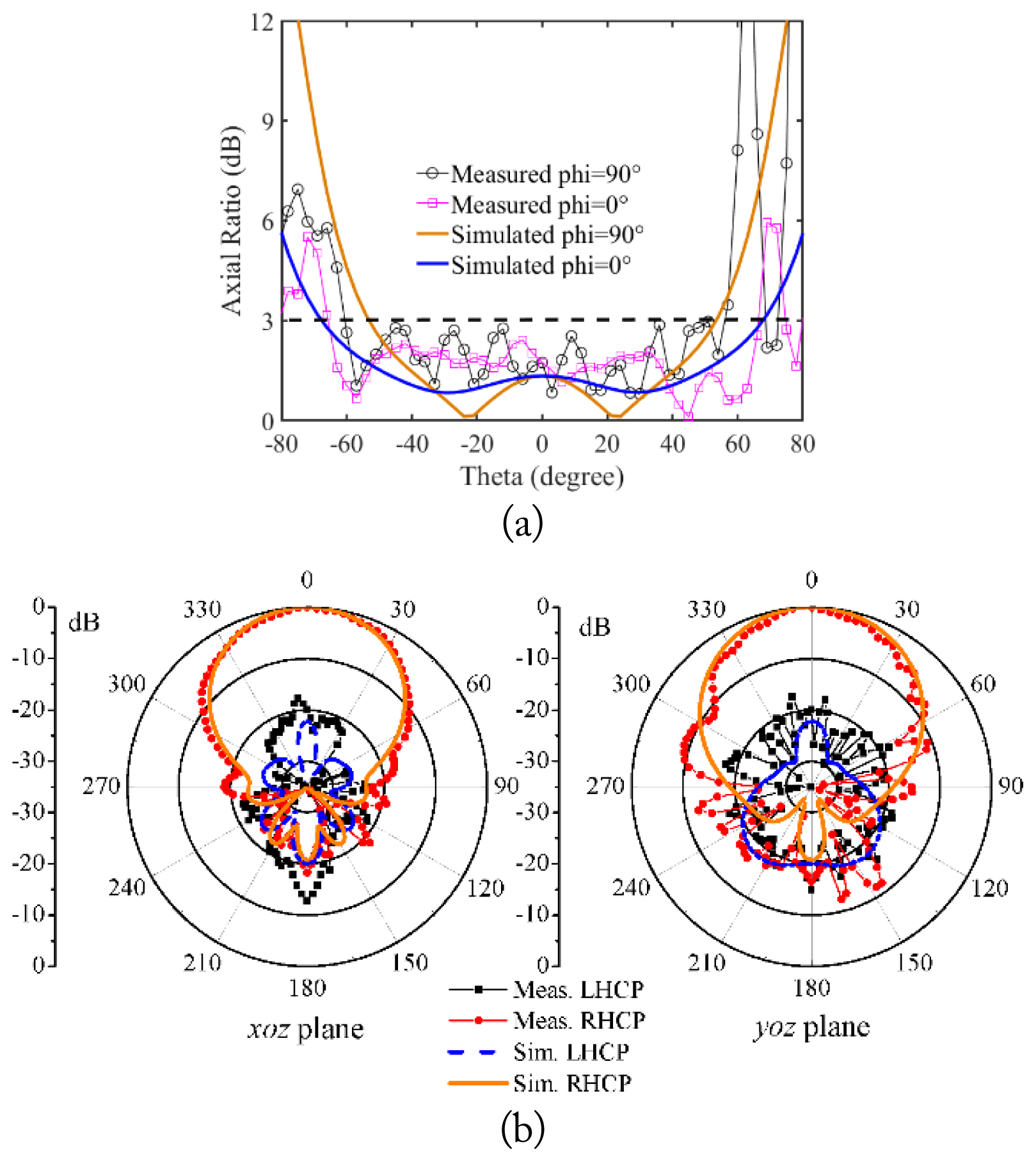
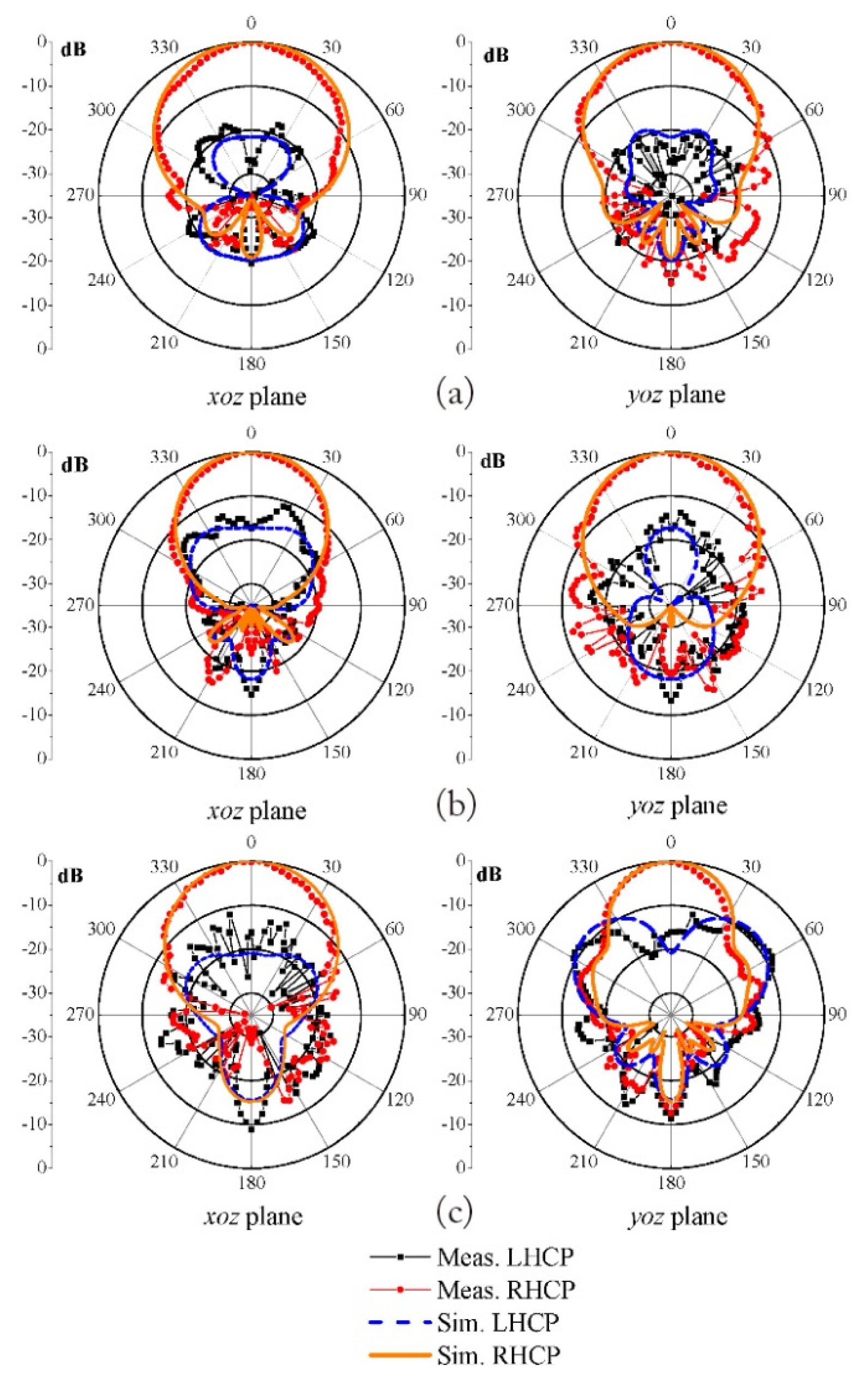
The differentially fed antenna demonstrates the characteristics of a large ARBW, as verified by simulation and experiment. As shown in Fig. 9(a), the ARBWs of 132.3° in the xoz plane and 116.2° in the yoz plane are realized at 5.5 GHz. The simulated and measured normalized radiation patterns at 5.5 GHz are shown in Fig. 9(b). Fig. 10 demonstrates the normalized radiation patterns at significant frequencies of 5.2, 6, and 6.8 GHz. The normalized right-hand CP is clearly greater than the normalized left-hand CP in the z-axis direction. The measured radiation patterns closely resemble those obtained from simulation, indicating a high degree of similarity.

IV. Performance Comparison

Table 1 provides a comparison of various parameters, including thickness, bandwidth, and peak gain, for different antennas. The crossed-dipole antennas in [810] showed a wide −10-dB impedance bandwidth and 3-dB ARBW, but they had a high profile. The CP antennas in [1114] exhibited a wide 3-dB ARBW but suffered from a limited 3-dB ARBW. The antennas in [20, 23, 26] were low-profile metasurface-based designs. In [20, 23], incomplete ground planes were used to achieve 3-dB ARBWs of 14.9% and 20.9%, respectively. A 3-dB ARBW of 17.5% was achieved with the antenna in [26] fed by a slotted patch. The differentially fed CP antennas in [29, 30] with a high profile showed a wide 3-dB ARBW, but the peak gain was less than 8.5 dBic.

V. Conclusion

This paper presents a novel differentially fed antenna design with a wide 3-dB ARBW and a wide ARBW. We compared the resonant frequencies and mode currents of a conventional dipole antenna and a bending dipole antenna to identify the resonant modes responsible for CP radiation and determine the source of the phase difference in the orthogonal mode current. Our findings reveal that placing the bending dipole excitation structure in the same plane as the unit cell radiation structure enables the generation of a broad 3-dB ARBW. Experimental results demonstrate that our proposed differentially fed CP antenna exhibits an impressive ARBW of 132.3° in the xoz plane and 116.2° in the yoz plane at 5.5 GHz.
Furthermore, our results show a measured (10 dB) impedance bandwidth of 78.8% (3.81–8.76 GHz) and a measured (3-dB) ARBW of 36.7% (4.78–6.93 GHz). It is worth noting that the overlapping bandwidth indicates excellent AR performance for this antenna design.

Fig. 1
Structure of the presented CP antenna: (a) three-dimensional view, (b) side view, (c) top view, and (c) bottom view.
jees-2023-6-r-196f1.jpg
Fig. 2
Evolution of the proposed antenna.
jees-2023-6-r-196f2.jpg
Fig. 3
Simulated results of different evolution antennas: (a) reflection coefficient and (b) axial ratio.
jees-2023-6-r-196f3.jpg
Fig. 4
(a) Mode current and resonant frequency of the dipoles in free space. (b) Mode current, resonant frequency, and axial ratio of the bending dipole in free space.
jees-2023-6-r-196f4.jpg
Fig. 5
(a) State A: unit cell structure on top of the feeding structure. (b) State B: unit cell structure underneath the feeding structure. (c) Simulation results for reflection coefficients in states A, B (the final structure), and C. (d) Simulation results for axial ratio in states A, B (the final structure), and C.
jees-2023-6-r-196f5.jpg
Fig. 6
Simulated results of varying L2: (a) reflection coefficient and (b) axial ratio.
jees-2023-6-r-196f6.jpg
Fig. 7
Photograph of the fabricated antenna.
jees-2023-6-r-196f7.jpg
Fig. 8
Simulated and measured results of the proposed differentially fed CP antenna: (a) reflection coefficient and (b) AR and gain.
jees-2023-6-r-196f8.jpg
Fig. 9
Simulated and measured results of the proposed CP antenna at 5.5 GHz: (a) axial ratio in the xoz and yoz planes and (b) radiation patterns.
jees-2023-6-r-196f9.jpg
Fig. 10
Simulated and measured radiation patterns of the proposed antenna: (a) at 5.2 GHz, (b) at 6 GHz, and (c) at 6.8 GHz.
jees-2023-6-r-196f10.jpg
Table 1
Comparison of performance with other CP antennas
Study Dimension of λ0 −10 dB |S11| bandwidth (%) 3-dB ARBW (%) 3-dB ARBW (°) Peak gain (dBic) Antenna type Complete ground
Xu et al. [8] 0.4 × 0.4 × 0.17 @ 1.5 GHz 66.2 41.3 - ~7 Crossed-dipole Yes
Nguyen et al. [9] 0.57 × 0.57 × 0.24 @ 3 GHz 79.4 66.7 - 9.7 Crossed-dipole Yes
Feng et al. [10] 1.1 × 1.1 × 0.4 @ 4.4 GHz 93.1 90.9 - 8.6 Crossed-dipole Yes
Nasimuddin et al. [11] 0.373 × 0.373 × 0.016 @ 1.58 GHz 3.5 1.5 180, 180 5.25 Patch Yes
Vignesh et al. [12] 0.475 × 0.475 × 0.013 @ 2.5 GHz 4.4 2.2 176, 176 4.5 Patch Yes
Ray et al. [13] 0.289 × 0.289 × 0.013 @ 2.48 GHz 3.4 0.93 226, 198 3.87 Patch Yes
Chen et al. [14] 0.448 × 0.448 × 0.064 @ 1.58 GHz 20.8 8.5 190, 190 5.3 Array Yes
Jia et al. [20] 1.16 × 1.16 × 0.06 @ 5.4 GHz 21 14.9 - 9.3 Metasurface No
Gao et al. [23] 1 × 1 × 0.07 @ 5.5 GHz 28.2 20.9 - 9.7 Metasurface No
Yang et al. [26] 0.99 × 0.99 × 0.07 @ 5.5 GHz 35.1 17.5 - 8.5 Metasurface Yes
Tu et al. [29] 1.03 × 1.03 × 0.25 @ 2.18 GHz 57.2 31.1 - ~6.5 Differentially fed Yes
Wen et al. [30] 1.26 × 1.26 × 0.27 @ 2.69 GHz 62.17 55.6 - 8.1 Differentially fed Yes
This work 1.546 × 1.543 × 0.12 @ 5.8 GHz 78.8 36.7 132.3, 116.2 10.2 Differentially fed Yes

References

1. F. Zhu, Q. Luo, and S. Gao, Circularly Polarized Antennas. Hoboken, NJ: Wiley, 2013.

2. F. Ferrero, C. Luxey, G. Jacquemod, and R. Staraj, "Dual-band circularly polarized microstrip antenna for satellite applications," IEEE Antennas and Wireless Propagation Letters, vol. 4, pp. 13–15, 2005. https://doi.org/10.1109/LAWP.2004.841622
crossref
3. C. Deng, X. Lv, and Z. Feng, "Low-profile circularly polarised patch-ring antenna with compact feeding network," IET Microwaves Antennas & Propagation, vol. 12, no. 3, pp. 410–415, 2017. https://doi.org/10.1049/iet-map.2017.0637
crossref
4. Y. X. Guo and D. C. H. Tan, "Wideband single-feed circularly polarized patch antenna with conical radiation pattern," IEEE Antennas and Wireless Propagation Letters, vol. 8, pp. 924–926, 2009. https://doi.org/10.1109/LAWP.2009.2028909
crossref
5. N. Yan, K. Ma, and Y. Luo, "An SISL sequentially rotated feeding circularly polarized stacked patch antenna array," IEEE Antennas and Wireless Propagation Letters, vol. 68, no. 3, pp. 2060–2067, 2020. https://doi.org/10.1109/TAP.2019.2957096
crossref
6. K. Ding, C. Gao, D. Qu, and Q. Yin, "Compact broadband circularly polarized antenna with parasitic patches," IEEE Transactions on Antennas and Propagation, vol. 65, no. 9, pp. 4854–4857, 2017. https://doi.org/10.1109/TAP.2017.2723938
crossref
7. L. Wang, Z. Zhu, and Y. En, "Performance enhancement of broadband circularly polarized slot–microstrip antenna using parasitic elements," IEEE Antennas and Wireless Propagation Letters, vol. 20, no. 12, pp. 2255–2259, 2021. https://doi.org/10.1109/LAWP.2021.3104850
crossref
8. R. Xu, J. Y. Li, and W. Kun, "A broadband circularly polarized crossed-dipole antenna," IEEE Transactions on Antennas and Propagation, vol. 64, no. 10, pp. 4509–4513, 2016. https://doi.org/10.1109/TAP.2016.2588523
crossref
9. T. K. Nguyen, H. H. Tran, and N. Nguyen-Trong, "A wideband dual-cavity-backed circularly polarized crossed dipole antenna," IEEE Antennas and Wireless Propagation Letters, vol. 16, pp. 3135–3138, 2017. https://doi.org/10.1109/LAWP.2017.2764923
crossref
10. G. Feng, L. Chen, X. Wang, X. Xue, and X. Shi, "Broadband circularly polarized crossed bowtie dipole antenna loaded with parasitic elements," IEEE Antennas and Wireless Propagation Letters, vol. 17, no. 1, pp. 114–117, 2018. https://doi.org/10.1109/LAWP.2017.2777442
crossref
11. Nasimuddin, Y. S. Anjani, and A. Alphones, "A widebeam circularly polarized asymmetric-microstrip antenna," IEEE Transactions on Antennas and Propagation, vol. 63, no. 8, pp. 3764–3768, 2015. https://doi.org/10.1109/TAP.2015.2438397
crossref
12. S.B. Vignesh, Nasimuddin, and A. Alphones, "Stubs-integrated-microstrip antenna design for wide coverage of circularly polarised radiation," IET Microwaves, Antennas & Propagation, vol. 11, no. 4, pp. 444–449, 2017. https://doi.org/10.1049/iet-map.2016.0366
crossref
13. M. K. Ray, K. Mandal, and N. Nasimuddin, "Low-profile circularly polarized patch antenna with wide 3 dB beamwidth," IEEE Antennas and Wireless Propagation Letters, vol. 18, no. 12, pp. 2473–2477, 2019. https://doi.org/10.1109/LAWP.2019.2940703
crossref
14. X. Chen, D. Wu, L. Yang, and G. Fu, "Compact circularly polarized microstrip antenna with cross-polarization suppression at low-elevation angle," IEEE Antennas and Wireless Propagation Letters, vol. 16, pp. 258–261, 2017. https://doi.org/10.1109/LAWP.2016.2571303
crossref
15. K. L. Wong and T. W. Chiou, "Broad-band single-patch circularly polarized microstrip antenna with dual capacitively coupled feeds," IEEE Transactions on Antennas and Propagation, vol. 49, no. 1, pp. 41–44, 2001. https://doi.org/10.1109/8.910527
crossref
16. C. Lin, F. S. Zhang, Y. C. Jiao, F. Zhang, and X. Xue, "A three-fed microstrip antenna for wideband circular polarization," IEEE Antennas and Wireless Propagation Letters, vol. 9, pp. 359–362, 2010. https://doi.org/10.1109/LAWP.2010.2048296
crossref
17. S. Fu, Q. Kong, S. Fang, and Z. Wang, "Broadband circularly polarized microstrip antenna with coplanar parasitic ring slot patch for L-band satellite system application," IEEE Antennas and Wireless Propagation Letters, vol. 13, pp. 943–946, 2014. https://doi.org/10.1109/LAWP.2014.2323113
crossref
18. X. Chen, L. Yang, J. Y. Zhao, and G. Fu, "High-efficiency compact circularly polarized microstrip antenna with wide beamwidth for airborne communication," IEEE Antennas and Wireless Propagation Letter, vol. 15, pp. 1518–1521, 2016. https://doi.org/10.1109/LAWP.2016.2517068
crossref
19. K. L. Chung, Y. Li, and C. Zhang, "Broadband artistic antenna array composed of circularly-polarized Wangshaped patch elements,” A," EU-International Journal of Electronics and Communications, vol. 74, pp. 116–122, 2017. https://doi.org/10.1016/j.aeue.2017.02.006
crossref
20. Y. Jia, Y. Liu, S. Gong, W. Zhang, and G. Liao, "A low-RCS and high-gain circularly polarized antenna with a low profile," IEEE Antennas and Wireless Propagation Letters, vol. 16, pp. 2477–2480, 2017. https://doi.org/10.1109/LAWP.2017.2725380
crossref
21. S. Liu, D. Yang, and J. Pan, "A low-profile broadband dual-circularly-polarized metasurface antenna," IEEE Antennas and Wireless Propagation Letters, vol. 18, no. 7, pp. 1395–1399, 2019. https://doi.org/10.1109/LAWP.2019.2917758
crossref
22. M. A. Matin, B. S. Sharif, and C. C. Tsimenidis, "Dual layer stacked rectangular microstrip patch antenna for ultra wideband applications," IET Microwaves, Antennas & Propagation, vol. 1, no. 6, pp. 1192–1196, 2007. https://doi.org/10.1049/iet-map:20070051
crossref
23. X. Gao, G. Tian, Z. Shou, and S. Li, "A low-profile broadband circularly polarized patch antenna based on characteristic mode analysis," IEEE Antennas and Wireless Propagation Letters, vol. 20, no. 2, pp. 214–218, 2021. https://doi.org/10.1109/LAWP.2020.3044320
crossref
24. S. X. Ta and I. Park, "Low-profile broadband circularly polarized patch antenna using metasurface," IEEE Transactions on Antennas and Propagation, vol. 63, no. 12, pp. 5929–5934, 2015. https://doi.org/10.1109/TAP.2015.2487993
crossref
25. C. Li, X. W. Zhu, P. Liu, C. Yu, and W. Hong, "A metasurface-based multilayer wideband circularly polarized patch antenna array with a parallel feeding network for Q-Band," IEEE Antennas and Wireless Propagation Letters, vol. 18, no. 6, pp. 1208–1212, 2019. https://doi.org/10.1109/LAWP.2019.2912624
crossref
26. H. Yang, X. Liu, and Y. Fan, "Design of broadband circularly polarized all-textile antenna and its conformal array for wearable devices," IEEE Transactions on Antennas and Propagation, vol. 70, no. 1, pp. 209–220, 2022. https://doi.org/10.1109/TAP.2021.3098542
crossref
27. Y. Luo and Q. X. Chu, "Oriental crown-shaped differentially fed dual-polarized multidipole antenna," IEEE Transactions on Antennas and Propagation, vol. 63, no. 11, pp. 4678–4685, 2015. https://doi.org/10.1109/TAP.2015.2478909
crossref
28. Z. Tang, J. Liu, Y. M. Cai, J. Wang, and Y. Yin, "A wide-band differentially fed dual-polarized stacked patch antenna with tuned slot excitations," IEEE Transactions on Antennas and Propagation, vol. 66, no. 4, pp. 2055–2060, 2018. https://doi.org/10.1109/TAP.2018.2800764
crossref
29. Z. H. Tu, K. G. Jia, and Y. Y. Liu, "A differentially fed wideband circularly polarized antenna," IEEE Antennas and Wireless Propagation Letters, vol. 17, no. 5, pp. 861–864, 2018. https://doi.org/10.1109/LAWP.2018.2820082
crossref
30. L. H. Wen, S. Gao, Q. Luo, Q. Yang, W. Hu, Y. Yin, J. Wu, and X. Ren, "A wideband series-fed circularly polarized differential antenna by using crossed open slot-pairs," IEEE Transactions on Antennas and Propagation, vol. 68, no. 4, pp. 2565–2574, 2020. https://doi.org/10.1109/TAP.2019.2951994
crossref

Biography

jees-2023-6-r-196f11.jpg
Wen Li, https://orcid.org/0009-0008-1640-265X was born in Shandong, China. He obtained his M.S. degree from Qingdao University of Technology, Shandong, China, in 2020. He is currently pursuing a Ph.D. in information and communication engineering at Harbin Engineering University, China. His current research interests include circularly polarized antennas and MIMO antennas.

Biography

jees-2023-6-r-196f12.jpg
Wei Xue, https://orcid.org/0000-0003-1104-0959 received his B.S. and M.S. degrees in communication and information system from Harbin Engineering University, Harbin, China, in 1995 and 2001, respectively, and his Ph.D. from St. Petersburg State Polytechnical University, Russia, in 2007. Presently, he holds the position of Professor within the Department of Information and Communication Engineering at Harbin Engineering University. His ongoing research focuses on various areas, including underwater and underground current field communications, efficient spectrum modeling, and simulation.

Biography

jees-2023-6-r-196f13.jpg
Yingsong Li, https://orcid.org/0000-0002-2450-6028 earned his B.S. degree in electrical and information engineering and M.S. degree in electromagnetic field and microwave technology from Harbin Engineering University in 2006 and 2011, respectively. He received his Ph.D. from both Kochi University of Technology (KUT), Japan, and Harbin Engineering University (HEU), China, in 2014. Currently, he serves as a full professor at the School of Electronic and Information Engineering at Anhui University since March 2022. He was a full professor at HEU from 2014 to 2022; a visiting scholar at the University of California, Davis, from March 2016 to March 2017; a visiting professor at the University of York, UK, in 2018; and a visiting professor at Far Eastern Federal University (FEFU) and KUT. Now, he holds the position of visiting professor at the School of Information at KUT since 2018. He is now a Fellow of Applied Computational Electromagnetics Society and is also a senior member of Chinese Institute of Electronics (CIE) and IEEE. He has authored and coauthored about 300 journal and conference papers in various areas of electrical and information engineering. His current research interests include signal processing, adaptive filters, metasurface designs, and microwave antennas.

Biography

jees-2023-6-r-196f14.jpg
Kwok L. Chung, https://orcid.org/0000-0002-5381-7327 (Ph.D., Senior Member, IEEE) was a research professor and a supervisor of Ph.D. students at Qingdao University of Technology (QUT) from Dec. 2005 to Jan. 2021. He also held the position of Director of Civionics Research Laboratory at QUT, where he led a cross-disciplinary research team for structural health monitoring. In April 2021, he joined Huizhou University as a distinguished professor. He has authored and coauthored about 180 publications, science citation index (SCI) and engineering index (EI), in various areas of electrical and civil engineering. His current research interests include passive wireless sensors, cement-based materials design and characterization, clothing antennas, and intelligent reconfigurable surfaces. Prof. Chung has been classified as the world’s top 2% scientists in the 2020 and 2021 lists released by Stanford University. He is the Founding Chair of the IEEE Qingdao AP/MTT/ COM joint chapter (CN10879) with Beijing Section. He has been an associate editor of IEEE Access and an associate editor of Elsevier Alexandria Engineering Journal since 2016 and 2020, respectively. He is an active reviewer for numerous international journals from IEEE, Elsevier, IOP science, and many others.

Biography

jees-2023-6-r-196f15.jpg
Zhixiang Huang, https://orcid.org/0000-0002-8023-9075 received his B.S. degree in statistics and probability and Ph.D. in electromagnetic field and microwave technology from Anhui University in 2002 and 2007, respectively. He was a lecturer at Anhui University from 2007 to 2008 and was promoted to the position of professor in 2008. He served as a visiting scholar in Ames Laboratory, Iowa State University, from 2010 to 2011. Currently, he is a full professor and serves as the Dean of the School of Electronic Information Engineering at Anhui University. He is also the founder of Key Laboratory of Electromagnetic Environmental Sensing of Anhui Higher Education Institutes. In addition, he holds the title of Director of the Young Scientists Club of Chinese Institute of Electronics (CIE) and is a member of the Youth Working Committee of CIE. He is the recipient of the Outstanding Young Talent Project of National Natural Science Foundation of China (NSFC) in 2018 and the Chang Jiang Scholars Program of Ministry of Education of the People’s Republic of China in 2022. He is a senior member of IEEE. He has more than 100 academic papers in peer-reviewed international/national journals. His current interests include theoretical and computational aspects of electromagnetics, microwave/RF circuit design, and multiphysics modeling.

ABOUT
ARTICLE CATEGORY

Browse all articles >

BROWSE ARTICLES
AUTHOR INFORMATION
Editorial Office
#706 Totoo Valley, 217 Saechang-ro, Yongsan-gu, Seoul 04376, Korea
Tel: +82-2-337-9666    Fax: +82-2-6390-7550    E-mail: admin-jees@kiees.or.kr                

Copyright © 2024 by The Korean Institute of Electromagnetic Engineering and Science.

Developed in M2PI

Close layer
prev next