I. Introduction
In recent years, ultra-wideband (UWB) technology has garnered significant attention owing to its remarkable capability for delivering high-resolution and precise positioning performance across a multitude of domains, including indoor positioning and radar systems [1]. UWB technology not only achieves centimeter-level precision through precise signal travel time measurements but also adeptly manages multipath propagation, thereby enhancing overall accuracy [2].
Circularly polarized (CP) antennas play a critical role in UWB applications by effectively preserving signal quality and mitigating multipath interference [3–5]. Notably, coplanar waveguide (CPW)-fed slot antennas can be seamlessly integrated into printed circuit boards (PCBs), thus facilitating the seamless infusion of UWB technology into diverse electronic devices [6]. In the context of CPW-fed slot antennas, various approaches have been proposed in the literature to produce CP characteristics. For example, one study achieved CP characteristics by employing symmetrical ground along with two inverse L-shaped ground strips [7].
This work proposes a novel CPW-fed CP slot antenna designed for UWB applications. In contrast to the approach employed in [7], the proposed antenna integrates a gamma-shaped monopole surrounded by an asymmetric ground equipped with gamma-shaped slits to achieve CP characteristics. Furthermore, this work investigates antenna and system fidelity factors to evaluate UWB pulse distortion, which is a critical aspect in the realm of UWB technology [8].
II. Design and Measurement
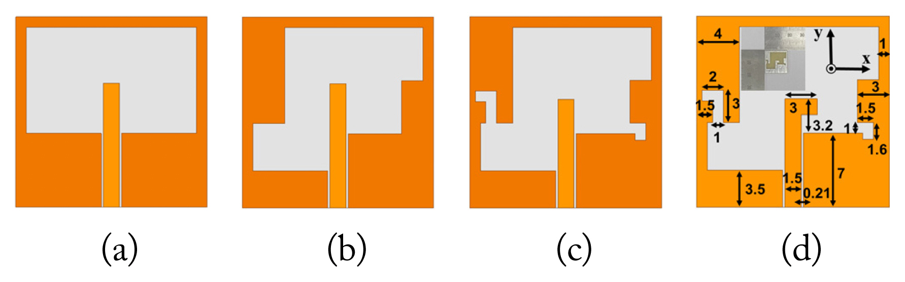
Fig. 1 illustrates the design and fabrication steps involved in creating the proposed antenna, including its final dimensions (unit: mm). All antennas were designed on an 18 mm × 18 mm FR4 substrate (ɛr = 4.4, tanδ = 0.02, h = 1.2 mm) and were excited by the CPW transmission line using a 50-Ω SMA connector.
Fig. 2 displays the reflection coefficient and axial ratio (AR) for each design step. The blue box represents the target operating frequency range (6.24–8.24 GHz) corresponding to UWB channels 5, 6, 8, and 9, with Ant.1 being a linearly polarized slot antenna designed for comparison purposes. To achieve circular polarization, Ant.2 incorporated asymmetric slots and a CPW ground, as shown in Fig. 1(b). However, its AR remained above 3 dB within the 6.66–9.33 GHz range, thus failing to meet the target frequencies. To address this issue, in Ant.3, gamma-shaped slits were added to the slot. Ant.3 achieved an AR below 3 dB within the 6.31–8.14 GHz band. Furthermore, to optimize the reflection coefficient and AR, the monopole shape was modified into a gamma shape in Ant.4. Consequently, the simulated reflection coefficients of the proposed antenna were found to be below −10 dB within the 5.74–9.18 GHz range, while the simulated AR was below 3 dB in the 6.14–8.52 GHz range, thus meeting the desired operating frequencies. Finally, the measured reflection coefficients of the proposed antenna remained below −10 dB above 6.10 GHz, while the measured AR was below 3 dB in the 5.70–8.50 GHz range, thus aligning with the target operating frequencies. The disparities between the measurement and simulation outcomes may be ascribed to inaccuracies stemming from fabrication and measurement procedures.
Fig. 3 illustrates the current distribution in the proposed antenna at 7.3 GHz. It is evident that the proposed antenna exhibits right-handed circular polarization (RHCP) characteristics in the +z direction and left-handed circular polarization (LHCP) characteristics in the −z direction.
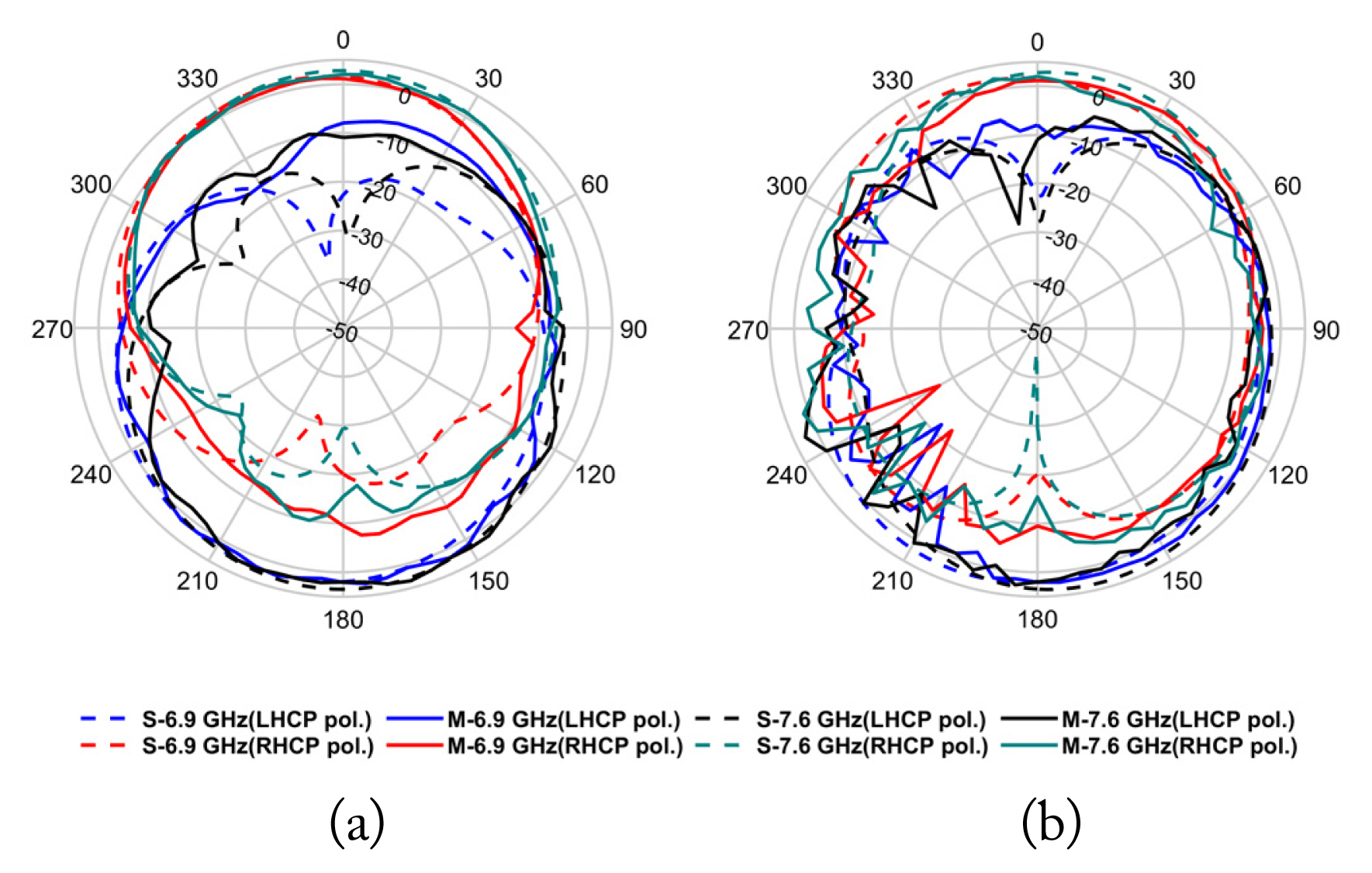
Furthermore, Fig. 4 depicts the radiation pattern of the proposed antenna in the xz- and yz-planes at two specific frequencies (6.9 GHz and 7.6 GHz) within the target UWB channel. The measured RHCP and LHCP radiation patterns are observed to be in close agreement with the simulation results of both planes. The simulated peak realized gains are recorded at 2.69 dBic and 3.77 dBic at 6.9 GHz and 7.6 GHz, respectively, while the measured peak realized gains are slightly higher, measuring 2.85 dBic and 4.02 dBic at 6.9 GHz and 7.6 GHz, respectively.
III. Time-Domain Analysis
This section analyzes the performance of the proposed antenna in the time domain using the CST electromagnetic simulator. The fidelity factors were computed by comparing the input pulse with the radiated E-fields. Furthermore, to investigate circular polarization attributes, this study conducted a cross-correlation analysis involving the input pulse and both the phi and theta components of radiated E-fields.
Fig. 5 illustrates the antenna fidelity factor (AFF) in both planes, considering both phi and theta polarizations. In the xz-plane, the AFF exceeds 0.9 for all angles in both polarizations. Meanwhile, in the yz-plane, the AFF is greater than 0.8 for all angles in the phi polarization, whereas it exceeds 0.8 for all angles in the theta polarization except for 270°, where the factor is valued at 0.70. This relatively low AFF at 270° may be attributed to significant fluctuations in gain across the operating frequency range.
Fig. 6 presents the normalized transmitted and received pulse signals, which were utilized to evaluate the system fidelity factor (SFF). For this purpose, two identical proposed antennas with a separation of 500 mm in both face-to-face and side-by-side configurations were arranged. The SFFs for the side-by-side and face-to-face setups were 92.5% and 98.4%, respectively.
IV. Conclusion
This letter introduces a novel CPW-fed CP slot antenna specifically designed for UWB applications. This antenna features innovative design elements, including an asymmetric ground equipped with gamma-shaped slits to achieve circular polarization and a gamma-shaped monopole to enhance reflection coefficients. Meticulous design optimization enables the proposed antenna to demonstrate consistent performance within the desired operating frequency range, which also aligns with UWB channels. The time-domain analysis shows good antenna fidelity, while the radiation patterns closely match the simulation results. Therefore, the proposed antenna exhibits great promise for UWB applications, in turn contributing to advancements in wireless communication and positioning technology.