I. Introduction
Microwave-based imaging has been widely used in many civil, industrial, and medical applications, such as nondestructive testing, visualization of the area behind a wall, and medical diagnosis [1]ŌĆō[5]. Specifically designed antennas are needed to meet the needs of microwave-based imaging applications where an antenna array is typically used. These antennas need to comply with several criteria to make them suitable for imaging applications, the most important of which relate to bandwidth, size, design complexity, and the cost of manufacturing [6]. Many types of antennas for microwave-based imaging applications have been proposed [7]ŌĆō[9]. These antennas mostly depend on their large size, structure complexity, or 3D-topology to obtain wideband and unidirectional radiation features. Microstrip patch antennas, which have the advantages of being low-profile, inexpensive, and easy to fabricate, can be a competitive candidate for microwave-based imaging systems. However, their narrow bandwidth represents a main limitation of their use [10].
Global optimization algorithms have been applied to patch antennas, such as genetic algorithm (GA), particle swarm optimization (PSO), and ant colony optimization (ACO) [11]ŌĆō[15]. Without optimizing a particular predefined geometry, fragment-type antennas have been reported to automatically generate a suitable antenna structure fulfilling the design requirements [16]ŌĆō[18]. However, most of these antennas have some drawbacks in terms of operation in a compact head imaging system, such as a high-cost substrate design, a large occupying area, or improper bandwidth.
In this paper, the design of a compact fragment-type patch antenna using a GA is proposed. The genetic algorithm implemented in Matlab operates on a 10-by-5 binary array encoded into a 50-bit (10 ├Ś 5) string. The proposed antenna fabricated-with a low-cost FR4 substrate has wide bandwidth and good gain. An array of 8 antennas is used for the microwave-based head imaging setup to identify hemorrhagic stroke successfully via the Microwave Radar Based Imaging Toolbox (MERIT) open-source software imaging tool [19ŌĆō22]. The imaging results validate the effectiveness of the proposed compact fragment-type patch antenna for the application of microwave-based head imaging.
This paper is organized as follows. Section II describes the design of the proposed compact fragment-type patch antenna. Section III presents the electromagnetic simulations and experimental results for the proposed antenna. The imaging setup and results are given in section IV. Finally, the summary and conclusion are given in section V.
II. Design of Proposed Fragment-Type Patch Antenna
A. Genetic Algorithm and Antenna Geometry
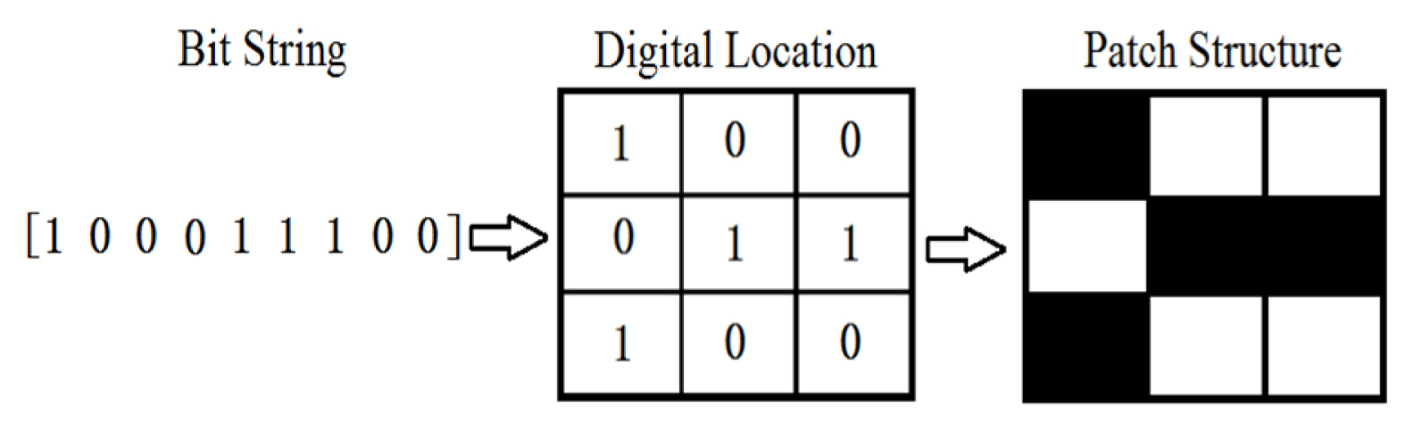
The relationship between the physical antenna structure and the resultant bit string is shown in Fig. 1. The layout of the fragment-type structure can be described by discretizing a design space into several small rectangular cells, which are assigned either ŌĆ£1ŌĆØ or ŌĆ£0ŌĆØ; cells marked with ŌĆ£1ŌĆØ are filled with metal cells.
The proposed fragment-type patch antenna is designed from an initial microstrip planar antenna model consisting of a rectangular patch and a rectangular ground plane (Fig. 2). The antenna is fed by a 50 ╬® microstrip line and printed on the FR4 substrate with a thickness of 0.5 mm. Table 1 shows the values of the initial microstrip planar antenna geometry parameters. The patch is discretized into 10 ├Ś 10 small rectangular cells. In order to reduce the computation, only half of the patch is optimized and mirrored along the longitudinal midline to create a symmetrical 10 ├Ś 10 element. Therefore, the genetic algorithm operates on a 10-by-5 binary array, which is encoded into a 50 bit (10 ├Ś 5) string. The genetic algorithm starts with a population of randomly generated solutions and then evolves them through selection, crossover, and mutation. The genetic algorithm is implemented in Matlab. The trial solutions are passed to a High Frequency Structure Simulator (HFSS), where the antenna geometry is generated. The design goal is to minimize S11 values in the 1.5 to 4.5 GHz range, which is suitable bands for biomedical imaging. The fitness function is:
(1)
where n is the number of frequency points; S11(fi) is the reflection coefficient of the sample fi. The population size is assigned to be 60 and evolved over 20 generations. A single run of HFSS on one trial solution antenna takes approximately 4 min on an Intel Corei5-4460 3.2 GHz PC. For the given population size and generations, 1200 such runs are necessary. This adds up to 3.3 days of runtime on a single machine. The optimized digital location is shown in equation (2).
B. Antenna Performance Analysis
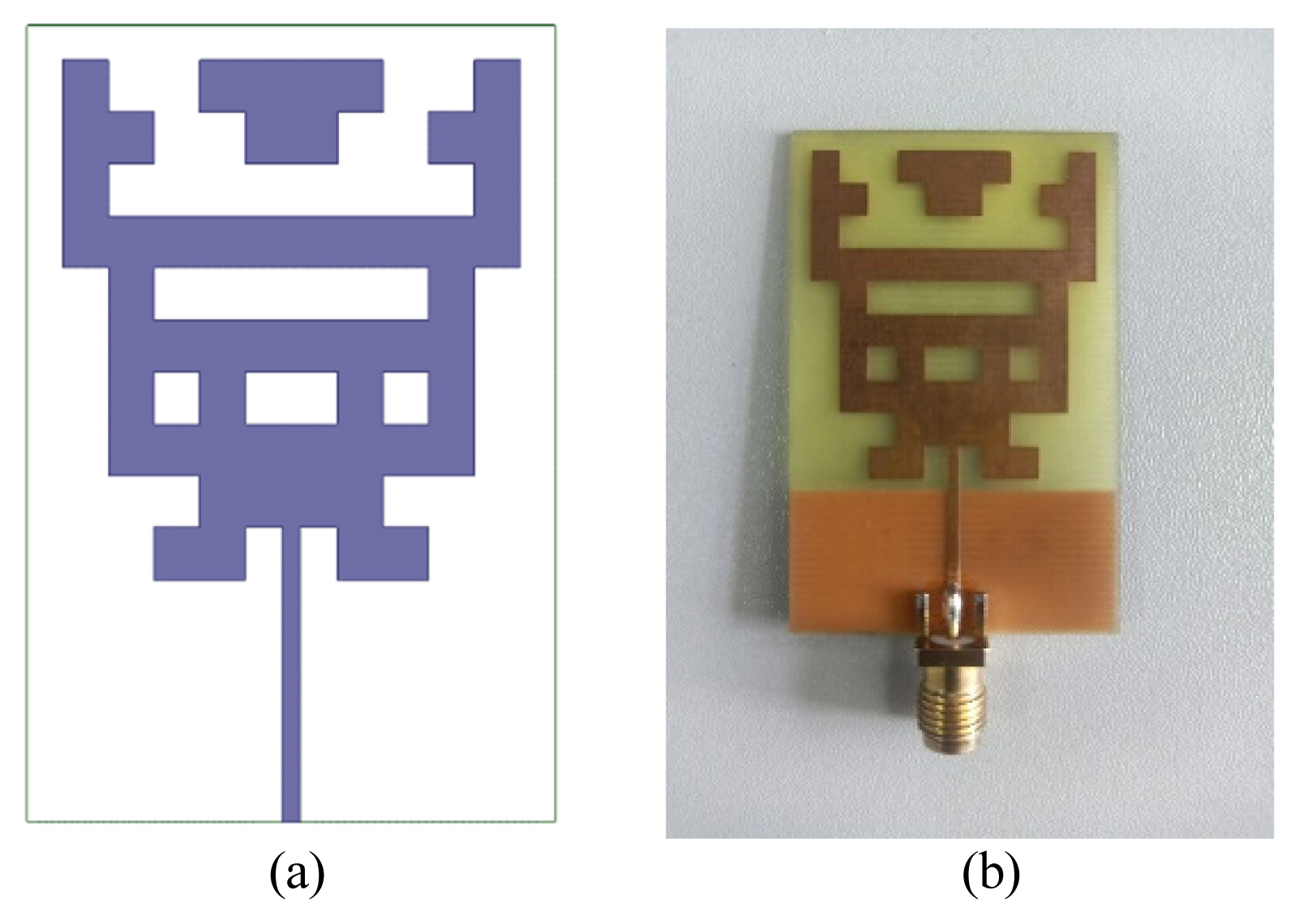
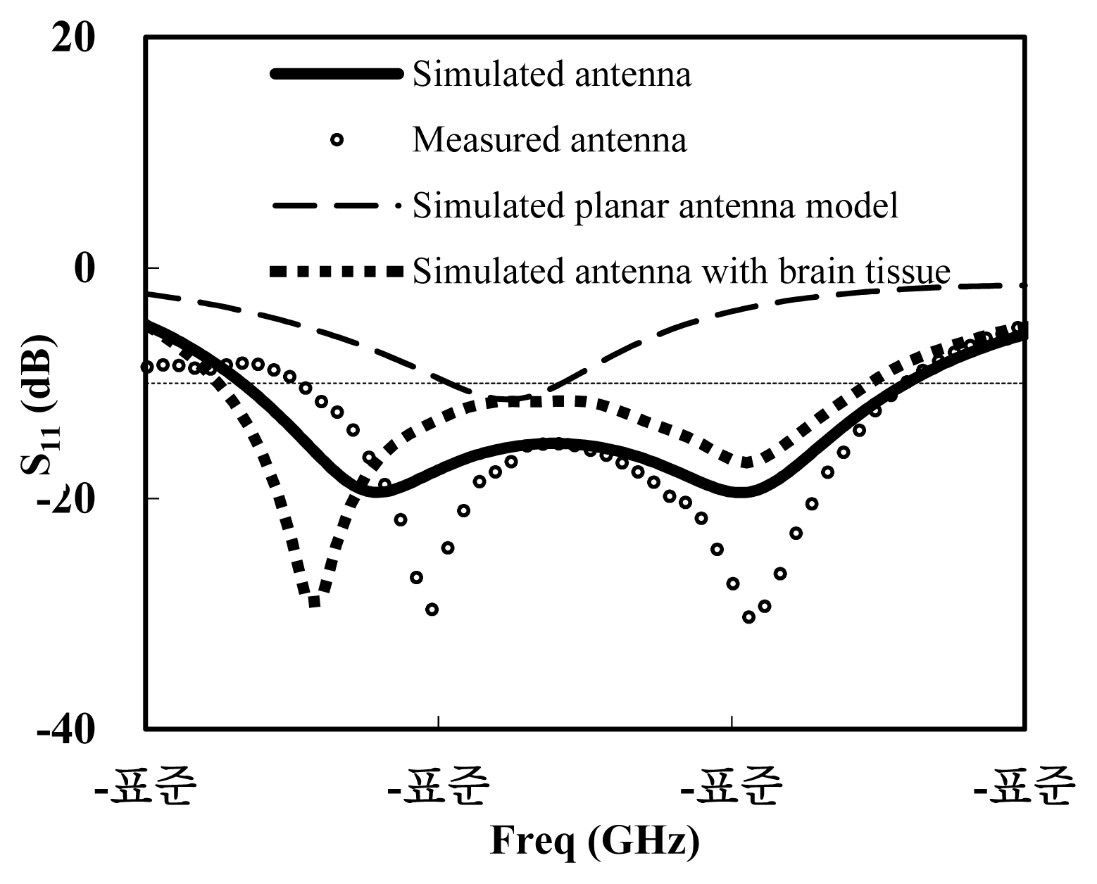
The final layout of the proposed fragment-type patch antenna optimized by the genetic algorithm and the physically fabricated antenna are shown in Fig. 3. A comparison of the computed and measured reflection coefficient (S11) results for the proposed fragment-type patch antenna and planar antenna model is presented in Fig. 4. The S-parameter was measured using the Agilent vector network analyzer N5227A. The results show that the antenna achieves an operating bandwidth of 2.18 GHz (1.92 to 4.1 GHz), and the overall structure of the proposed antenna is equivalent to 0.29 ╬╗0 ├Ś 0.19 ╬╗0 ├Ś 0.0032 ╬╗0, where ╬╗0 is the corresponding wavelength at 1.92 GHz. This is equivalent to 72.4% fractional bandwidth with a center frequency of 3.01 GHz.
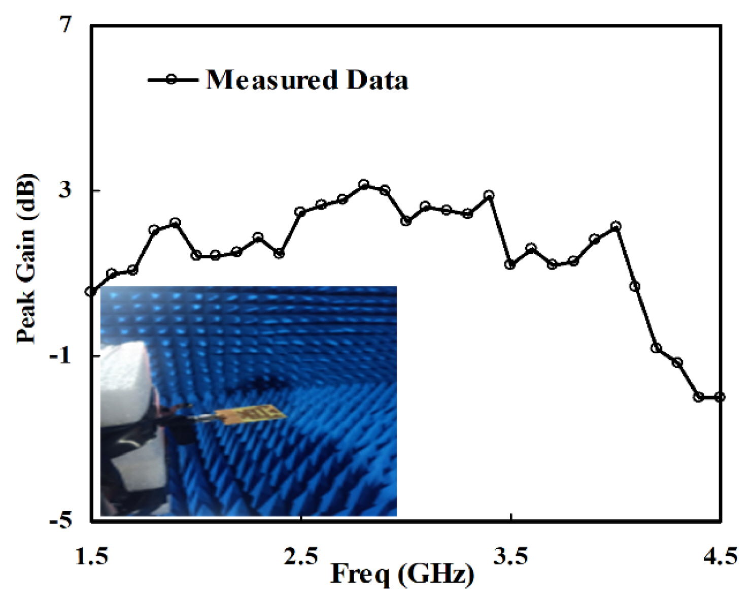
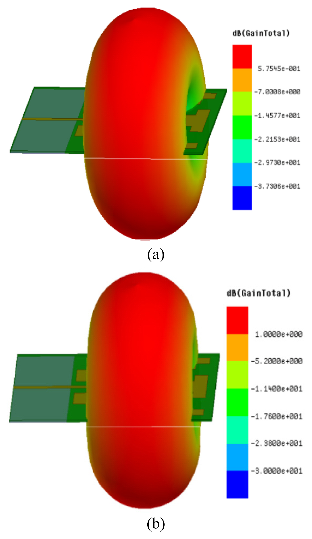
The variation of the measured peak realized gain (dB) with frequency is shown in Fig. 5. An average gain of more than 2.02 dBi is recorded with a maximum of 3.14 dBi at 2.80 GHz. Simulated 3-D radiation patterns of the proposed antennas at different frequencies are shown in Fig. 6. A rather smooth gain distribution is observed along the front side of antenna. This confirms that this antenna can enhance the received signal strength if the head model being investigated is placed along the front side of the antenna. It is obvious that a reasonably good agreement between the simulation and measurement has been found, indicating that the proposed antennas have reliable applications in microwave-based head imaging.
A comparison of reported antennas with the one proposed here is given in Table 2. The considered parameters are bandwidth, dimensions, and applications. It can be noted that the proposed antenna has a compact dimension and good bandwidth compared to the reported antennas.
III. Imaging Setup And Results
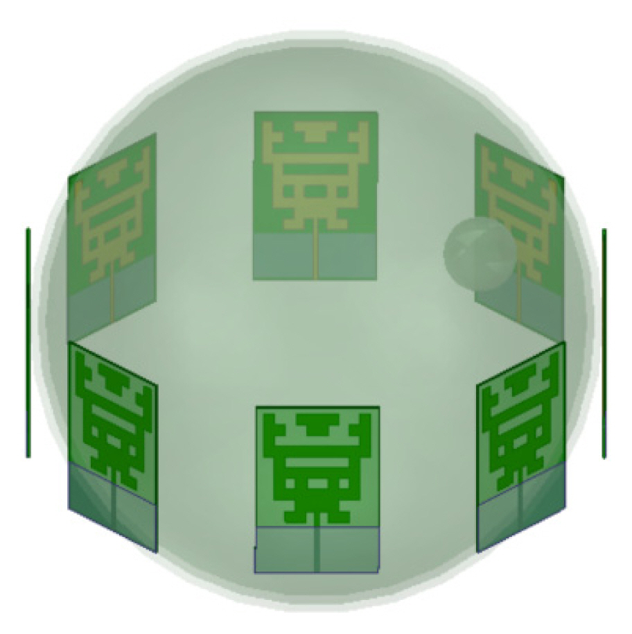
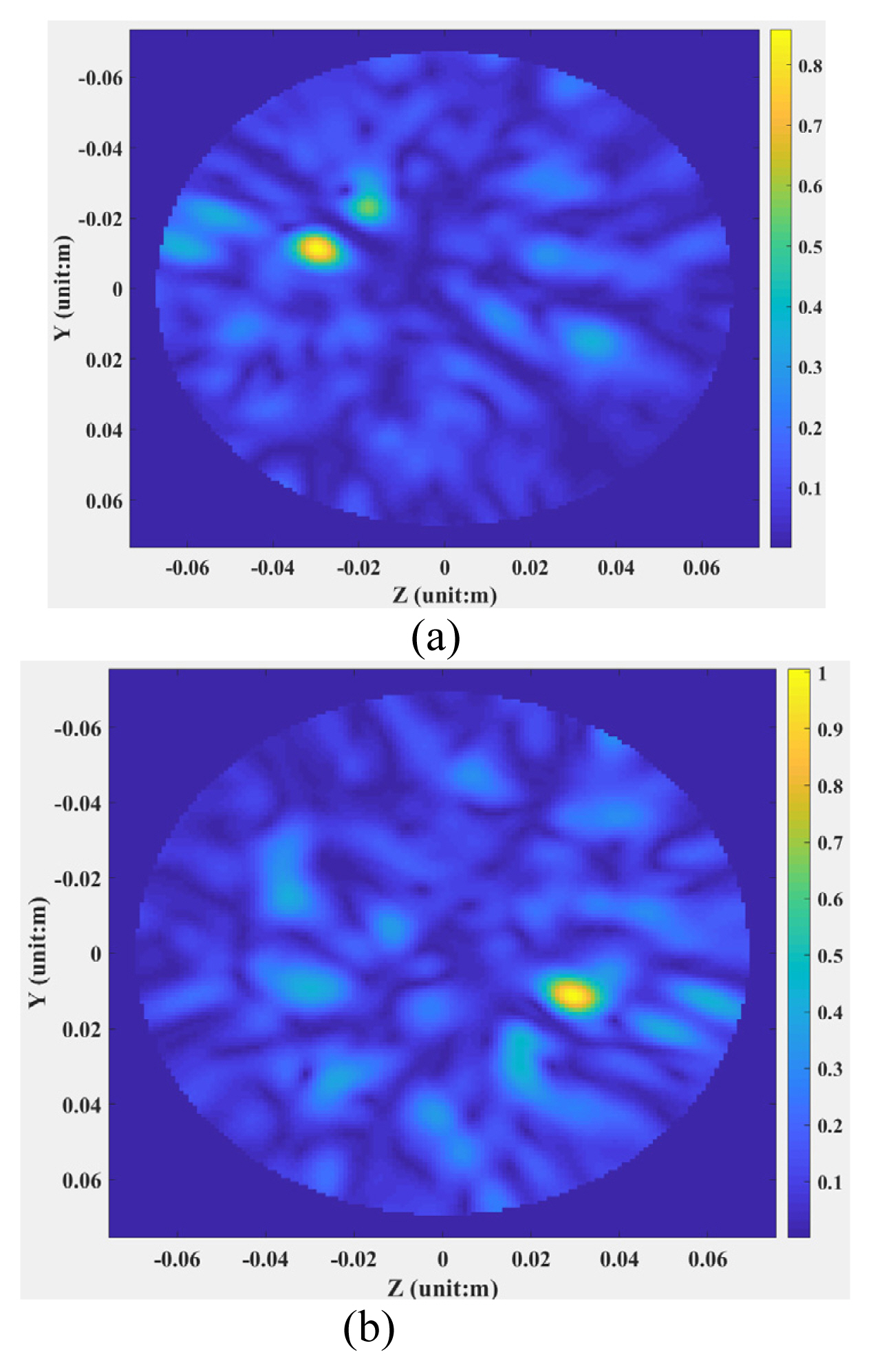
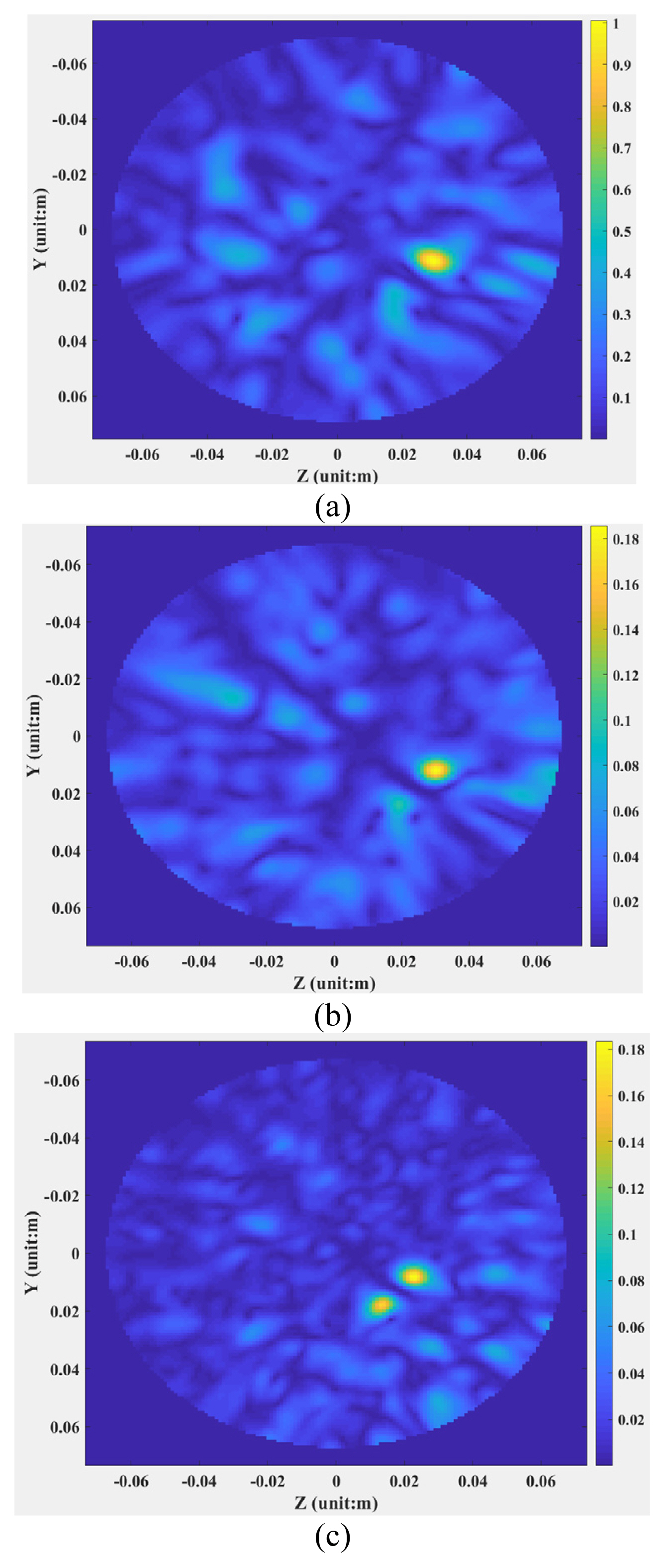
Eight proposed fragment-type patch antennas are deployed around the head phantom at an equal distance from each other, as depicted in Fig. 7. Among the 8 antennas, one antenna acts as a transmitter and the remaining 7 antennas act as a receiver for the backscattered signal from the head phantom. The process is repeated for each of the 8 antennas acting as a transmitter, and the total 56 (8 ├Ś 7) scanned positions are considered for a complete head phantom scan data set. Several homogeneous head phantoms are used to test the 8-antenna array performance in terms of the detection of hemorrhagic stroke using the HFSS simulation software. The tissuesŌĆÖ dielectric properties in the head phantoms are shown in Table 3. The distance between the antenna array and the head phantom is 2 mm. In case 1, the homogeneous head phantom is constructed with three layers of brain tissue consisting of a single medium, blood, and regular air layer. The radius of the brain tissue layer is 68 mm. The radius of the sphere blood with two different positions shown in Table 4 is 9 mm. In case 2, the homogeneous head phantom is constructed with four layers: skin, brain tissue, blood, and regular air. The width of the skin layer is 2 mm and the radius of the sphere brain tissue is 66 mm. In case 3, the homogeneous head phantom is constructed with five layers: skin, skull, brain tissue, blood, and regular air. The width of the skin is 2 mm, and the width of the skull is also 2 mm. The radius of the sphere brain tissue is 64 mm. The designed imaging system operates across the frequency band from 2 GHz to 4 GHz. The microwave propagates through the head phantoms and backscattering signals from various tissue layers. After taking the data from the mentioned imaging setup, the backscattered signal data is analyzed using the MERIT open-source software. MERIT provides free software algorithms for the Delay-and-Sum reconstruction of microwave imaging signals in medical and industrial settings. MERIT allows users to easily test different algorithms, easily switching between time and frequency domain signal representations. After processing the MERIT imaging toolbox, the imaging results are presented in Fig. 8 and Fig. 9. According to Fig. 8, the stroke response is clearly visible in the correct location. Reconstructed images of a hemorrhagic stroke for different homogeneous head phantoms are shown in Fig. 9. The stroke objects are clearly identified by a yellow color for all of the head phantoms. The results preliminarily confirm that the proposed system can be a good candidate for microwave imaging to detect hemorrhagic stroke through analyzing the backscattering signal efficiently.
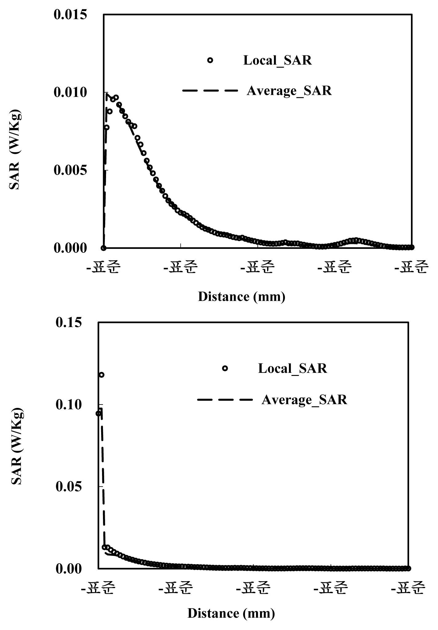
The influence of electromagnetic radiation on health has always been a hot topic of discussion. According to IEEE organization, the standard specific absorption rate (SAR) value for brain parts must be lower than 1.67 watts/kg. Fig. 10 shows the simulated local SAR and average SAR curves for the proposed head phantoms. In the simulation environment, the excitation signal power of the antenna is initially set to 1 mW. The maximum SAR value is 0.0097 W/kg for case one and 0.118 W/kg for case three, respectively. The distances from the antenna are 7.44 mm for case one and 3.36 mm for case three. According to the above-mentioned safety value of 1.67 W/Kg, 0.0097 and 0.118 are far less than 1.67. At this time, the amount of electromagnetic radiation absorbed by the brain is very small, and the impact on human health can be considered negligible.
IIIV. Summary And Conclusions
In this article, a compact fragment-type antenna using genetic algorithm has been proposed for a microwave-based head imaging application. The proposed antenna is designed from an initial microstrip planar antenna model consisting of a rectangular patch and a rectangular ground plane. The patch is discretized into symmetrical 10 ├Ś 10 small rectangular cells, and the genetic algorithm operates on a 10-by-5 binary array encoded into a 50-bit (10 ├Ś 5) string. The results show that the antenna achieves an operating bandwidth of 2.18 GHz and the overall structure of the proposed antenna is equivalent to 0.29 ╬╗0 ├Ś 0.19 ╬╗0. The setup imaging of an array of the 8 proposed antennas is designed with one antenna working as a transmitter and the others working as a receiver in turn. Several homogeneous head phantoms are used to test the 8-antenna array performance in terms of the detection of hemorrhagic stroke via the Microwave Radar-Based Imaging Toolbox open-source software. The results preliminarily confirm that the proposed compact fragment-type antenna system can be a good candidate for microwave head imaging to detect hemorrhagic stroke through efficiently analyzing the backscattering signal.